4-6 888-2408-002
WARNING: Disconnect primary power prior to servicing.
Overall System Theory
• Splitting of the IPA output into 2 equal amplitude signals 90 degrees out of phase,
by way of a 3dB hybrid, to drive the Z Plane dividers.
• Air flow sensing
• Ambient temperature sensing
• IPA 1 and IPA 2 interlocking
4.3.3.1 Main/Alternate Exciter Switching
Exciter selection is done via relay K1 and the EXCITER SELECT control signal
from the Life Support Board. The EXCITER SELECT signal is normally low which
places K1 in the position shown on the schematic, sending the Exciter 1 RF output
to the IPA input relay K2. If EXCITER SELECT goes high, K1 will be energized
and switches to the Exciter 2 RF output. This switching will take place
automatically if an exciter fault is detected by the Master Controller board. Exciter
switching can also be done manually using the Diagnostics display. Press [HOME,
STATUS D,C] (this code is explained in Section III, Operation). This should bring
up the screen in Figure 4-2. Pressing the D function key will now toggle K1,
switching from exciter 1 to exciter 2 or vise versa.
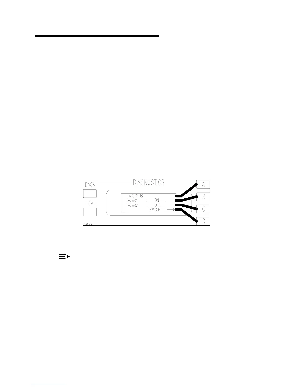
Figure 4-3 IPA Status Screen
[HOME, STATUS D,B]
NOTE:
For easy navigation through the Diagnostic menus, refer to “Using the Diag-
nostic Display” in Section III, Operation and to the “Diagnostics Display
Menu Tree”, in the schematic package, which gives a complete overview of
the Diagnostics menu structure.