2-16 888-2408-002
WARNING: Disconnect primary power prior to servicing.
Installation & Initial Turn-On
2.5.10 Initial Turn-on
Each transmitter is thoroughly checked out during factory final test but adjustment
may be required during installation due to shipping, variations in primary power,
antenna systems, or transmission line differences. Any remote or extended control
connections should be connected only after the transmitter is checked out and fully
operational. Refer to the Factory Test Data Sheets supplied with the transmitter for
typical meter readings. The transmitter was checked into a 50-ohm resistive load at
the Factory.
The Transmitter ON-OFF sequence is controlled by three separate buttons:
• HIGH
• LOW
• OFF
These buttons are located on the front panel of the Controller.
STEP 1 Activate the STATION AC POWER source to the transmitter.
STEP 2 Turn on the low voltage power supply breaker, CB1, located in the
rear of the transmitter cabinet in the upper right-hand corner. There
are 6 green LEDs on the Low Voltage Supply board which should be
illuminated. Close and secure the rear door.
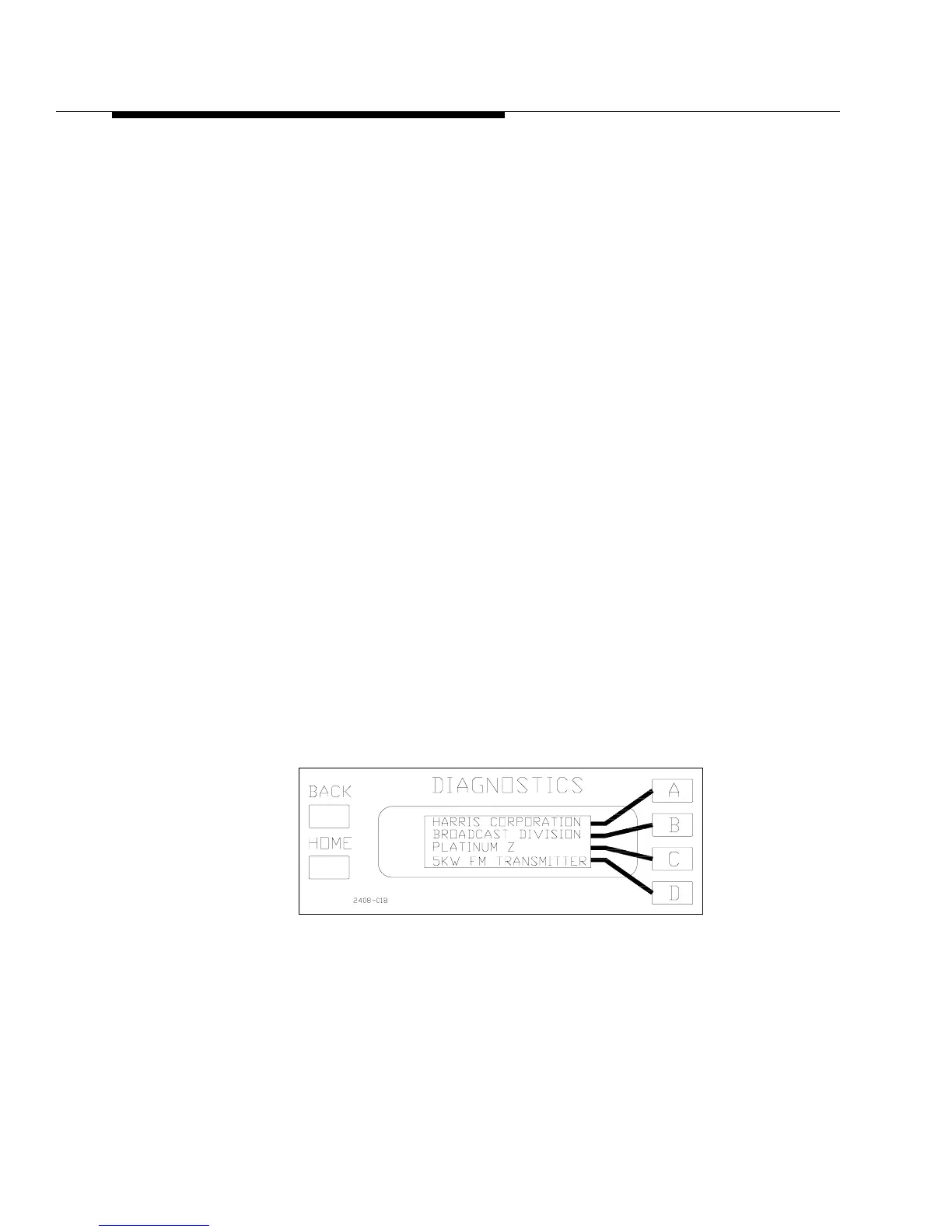
STEP 3 Verify that the two LCD displays on the front of the controller are
active. The Diagnostics display should look like Figure 2-5. The
Fault LED on the front panel will be lit, since the modules are not
installed yet, and should be ignored at this point.
Figure 2-5 Default Display
STEP 4 Press the PA VOLTS button on the front panel of the controller.
STEP 5 Press the LOW power ON button on the front of the controller, but
be ready to quickly press the off button if necessary. The PA VOLTS
reading on the front panel should be above 40Vdc and the blower
should come on at HIGH Speed.