2-10 888-2408-002
WARNING: Disconnect primary power prior to servicing.
Installation & Initial Turn-On
e. Wires #1 and #2 (orange cables tied up on the left side of the power supply
compartment) plug into the gray Wego block connector on the front of the
power supply tray. See Figure 2-3. Wire #1 goes to the left and #2 in the 3rd
hole from the left. Wires #40 and #41 are inserted into the 5th and 6th holes
respectively from the left. To insert the wires into the Wego block, insert a
screwdriver into the rectangular slot behind the wire hole and then carefully
push toward the rear of the transmitter. This will open the contact inside the
Wego block and the wire can be inserted. Be very careful not to let the wire
ends fray as the connectors are very close together and could cause a short.
The wire insulation should actually extend just inside the Wego block hole.
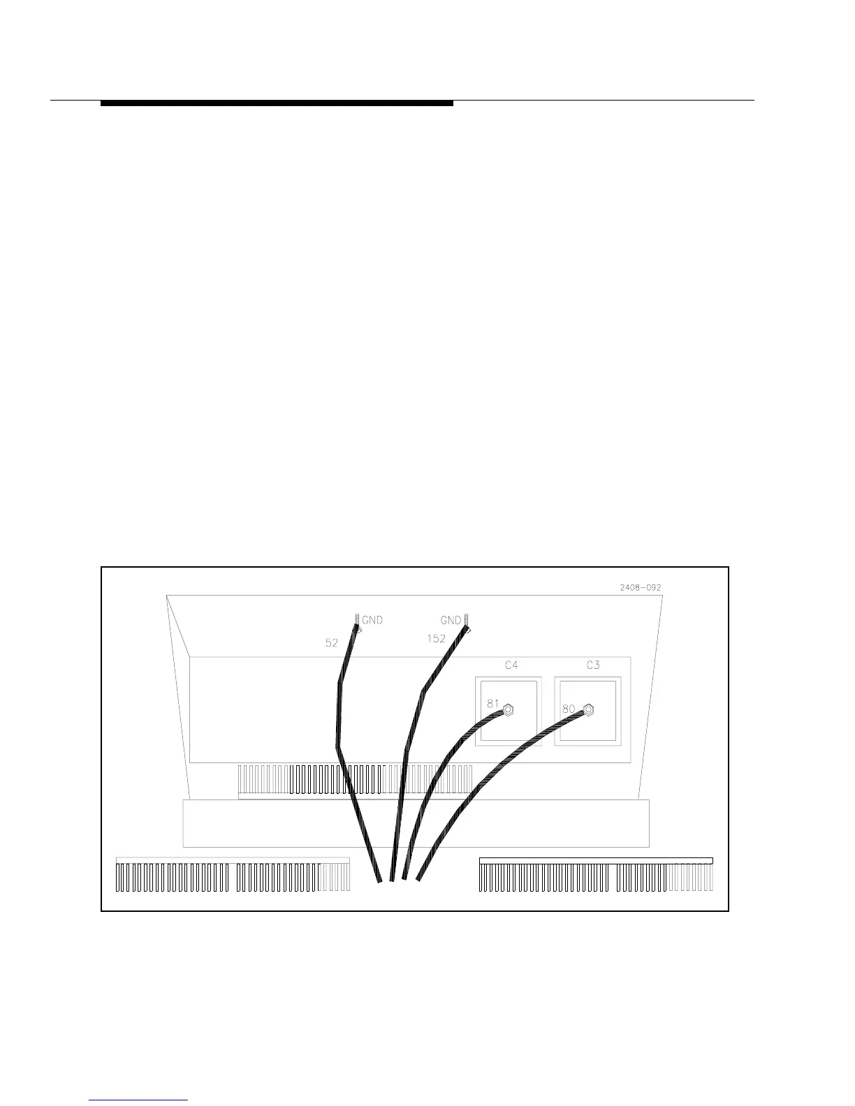
f. The large orange ground wires, #52 and 152, coming from the power supply
attach to the ground stud at the top-front edge of the power supply compart-
ment. It is located under the shelf which separates the power supply from the
PA compartment, see Figure 2-4.
g. Connect the safety ground wire to the stud on the front of the power supply
tray, just in front of A17TB1, See Figure 2-3.
h. Tighten the two hold down nuts located on the bottom front corners of the
power supply compartment.
Re-install the front cover panel for the power supply compartment.
Figure 2-4 DC and Ground Connections for Single Phase Power Supply