888-2408-002 2-19
WARNING: Disconnect primary power prior to servicing.
Installation & Initial Turn-On
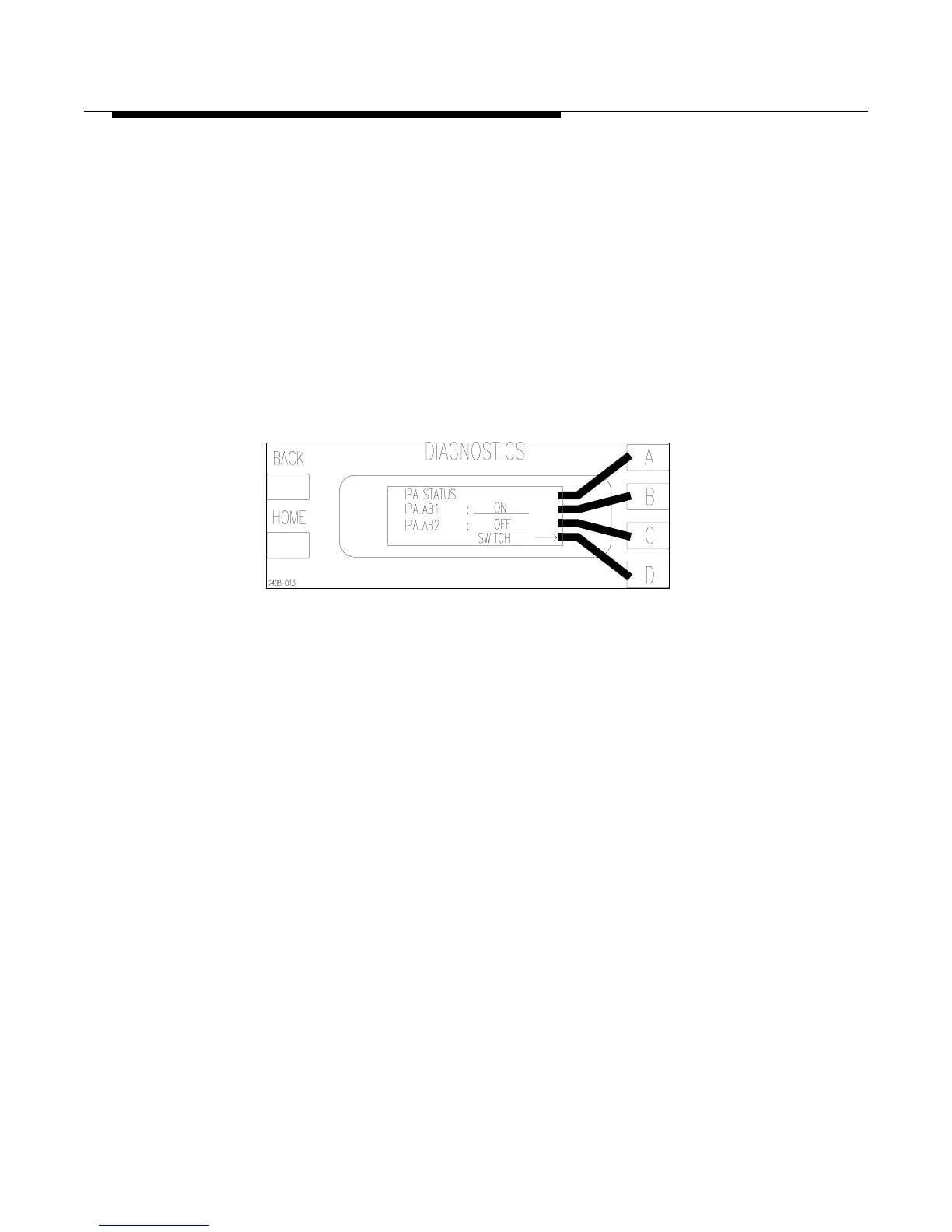
STEP 9 For the dual IPA configuration, the IPA will be identical to any of the
PA modules and may be plugged in with either side up in the IPA
slot. To see which IPA is active press [HOME, STATUS D,B]. This
should bring up the screen shown in Figure 2-8. If the transmitter is
configured with only a single IPA, then one half of the module will
be empty. It is recommended that the IPA module be inserted with
the amplifier on the right side of the heatsink. This places the
amplifier in the IPA_AB1 position (the default for the controller). If
the IPA is on the left side of the heatsink when inserted, then
IPA_AB2 will have to be selected before operating the transmitter.
To select IPA_AB2 press the [D] or switch key to toggle from
IPA_AB1 to IPA_AB2 and back.
Figure 2-8 IPA Status and Manual Switch
[HOME, STATUS D,B]
STEP 10 With all of the modules installed, the Fault LED on the controller
front panel should be flashing at this point. This indicates that there
are inactive faults in the fault log which need to be cleared at this
time. To reset the Fault Log press [FAULT, C, and then D for YES].
This will erase all inactive faults in the Fault Log and the front panel
Fault LED should be off. If the “FAULT” LED on the front panel of
the controller is not lit, then proceed to the next step.
If the “FAULT” LED, on the front panel of the controller, is
illuminated (not flashing), use the Fault Log to find the active
fault(s) and refer to Section VI, Troubleshooting for information on
how to track down the problem.
STEP 11 Turn the transmitter back ON at LOW power. Verify that the exciter
power is the same as the factory test data sheet. This can affect
performance.
The fan will run at high speed for 1 minute then will automatically
switch to low speed provided there are no faults. Any fault will
cause the fan to automatically switch to high speed. There is also an
option to force the fan speed to HIGH in the Configuration menus of
the Diagnostics Display. See Table 2-14 on page 2-24.