4-24 888-2408-002
WARNING: Disconnect primary power prior to servicing.
Overall System Theory
labeled SS1-B, SS2-B and SS3-B and are connected to the 48V taps on the
transformer “B” secondaries of T1 and T2. This allows the power supply to start
charging through R48, a 5 ohm 100W current limiting resistor. After about 2
seconds, the DRIVER 1 signal will activate the normal 48V tap SCRs which will tie
the taps directly to ground, bypassing R48.
4.5.1.2.3 PA Power Supply Discharge
The PA Power Supply Discharge circuit uses R48 to bleed down the supply
whenever the transmitter is turned off. The DISCHARGE signal is active low and
comes from the PS Controller Board. When low, it causes the output of U2-14 to go
high. This does two things:
a. First, it reverse biases CR31 which allows the gate of Q33 to pull high
through R54, thus shutting Q33 off. This removes the 10VB-SS used to acti-
vate the transformer taps. This prevents the PA Supply (and Soft Start) from
being activated while the DISCHARGE signal is active.
b. Second, it allows the base of Q37 to pull high, shutting it off. R62 will then
pull the gates of Q29 and Q31 low turning them on. Q29 and Q31 are
switches which tie the 52Vdc to R48, and the supply is discharged.
4.5.1.2.4 Voltage Samples
Two AC voltage samples are taken from the 48V taps using 301K ohm resistors.
One from the “A” secondary at J4-14 and one from the “B” secondary at J4-13. The
samples are pulsating DC with a frequency of 360Hz and an amplitude whose
average is equal to the DC power supply output. They are sent to the PS Controller
and used to control the tap switching based on the amplitude of the pulses. The
signals are also bandpass filtered at 60Hz to detect blown SCR fuses and 120Hz to
detect the loss of one AC input phase.
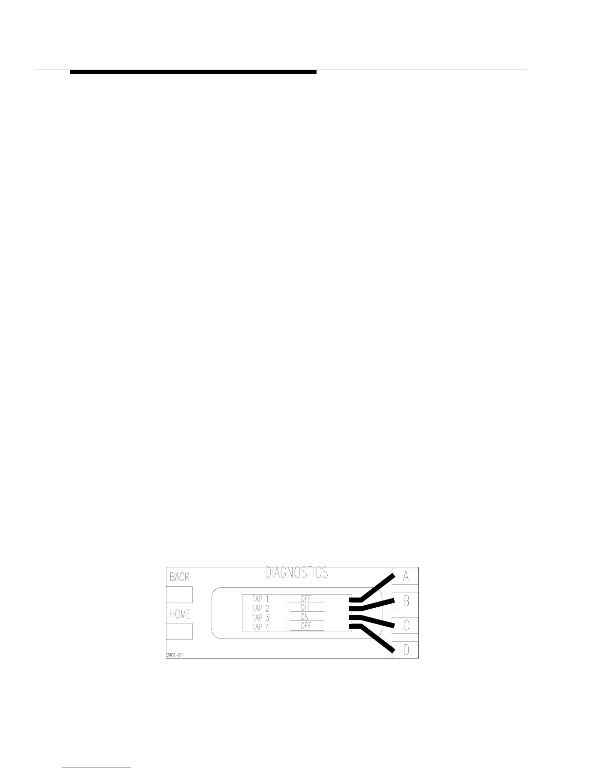
To determine if a tap has failed (blown fuse), refer to the Diagnostics Display. For
Power Supply 1, Press [HOME, STATUS, D,A,A,D] This will show you the screen
in Figure 4-12. Press D again to see the status of Tap 4. For Power Supply 2, Press
[HOME, STATUS, D,C,B,D].
Figure 4-12 Transformer Tap Status
[HOME, STATUS, D,A,A,D]