Page 8 of 43
3. Connecting and switching on the system
3.1 Connection
For operation, the plusoptiX A09 must be connected to a monitor and keyboard with a
mouse. The monitor must fulfill the following system requirements:
Resolution: 1024 x 768 pixels
Interface: VGA
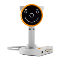
Four (4) USB ports of type A are available on the plusoptiX A09 for connecting e.g.
keyboard, mouse, printer or USB-sticks.
Where a monitor is already available at a workstation, a switch (monitor switch TK 207
by “Trendnet”) can be used to connect this monitor to the plusoptiX A09. This allows
you to save space by using the monitor for your practice network and for the plusoptiX
A09.
The plusoptiX A09 can also be attached to your practice network using an RJ-45
connection (network cable) via a GDT interface. Plusoptix supplies the software
required for operation via a GDT interface at no charge, should you wish to connect the
plusoptiX A09 to your network. In this case please consult your practice network
support personnel.
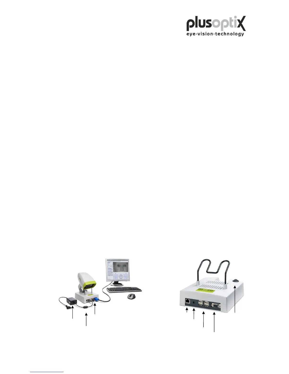
Fig. 1: Connect the VGA cable from the monitor to the plusoptiX A09. The keyboard
and mouse can be connected to the plusoptiX A09 by means of a USB cable or a
wireless USB adapter. Attach the 12V DC connector to the plusoptiX A09 and
the medical power unit to a 110 – 220 V AC (50 – 60 Hz) power plug. Ensure
that the power plug is switched off after close of business. This is a precaution in
case a short-circuit occurs during night-time which may cause a fire.
Fig. 2: Location of the connectors on the plusoptiX A09