4.20
ELECTRONIC FUEL INJECTION
P
RELIMINARY
V
ERS
I
ON
FUEL PUMP
Operation Overview
An electric fuel pump assembly is used to transfer fuel to the EFI
system from inside the fuel tank. This assembly includes the fuel
pump, fuel filters, regulator and fuel gauge sender. The pump is
rated for a minimum output of 25 liters per hour at 39 psi and has
two non-serviceable fuel filters.
When the key switch is turned to "ON", the ECU activates the
fuel pump, which pressurizes the system for start-up.
The ECU switches off the pump preventing the continued
delivery of fuel in these instances:
• If the key switch is not promptly turned to the "start"
position.
• If the engine fails to start
• If the engine is stopped with the key switch "on" (as in
the case of an accident).
In these situations, the “check engine” light will go on, but will
turn off after 4 cranking revolutions if system function is OK.
Once the engine is running, the fuel pump remains on.
Fuel Sender Test
If the fuel gauge reading on the instrument cluster is not
working, or if the display reading differs in large comparison to
the fuel in the tank, perform a resistance test on the fuel sender.
Disconnect the fuel pump / sending unit connection and measure
the resistance between the Purple and Brown wires (see chapter
10 for further details). If out of specification, replace the fuel
pump assembly.
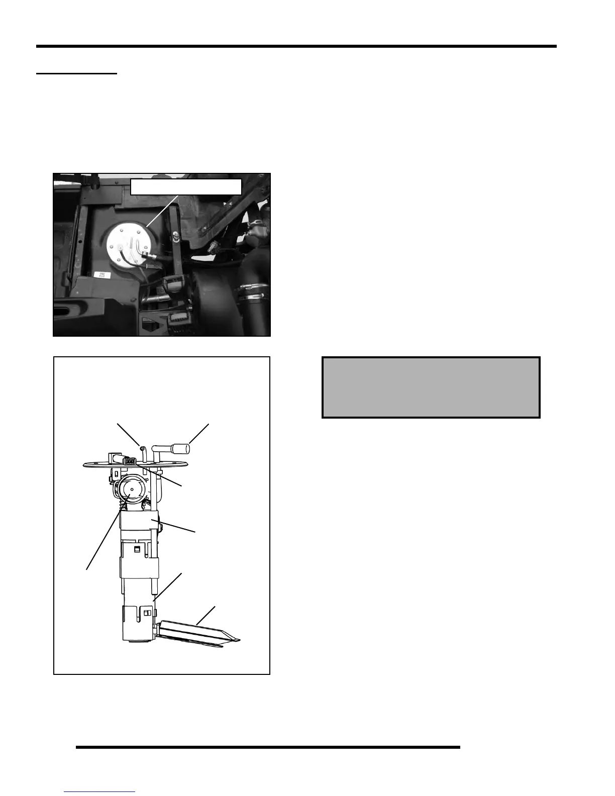
Fuel Pump Assembly
Located in Fuel Tank
Fuel Pump
Regulator
Pump / Sending Unit
Preliminary Filter
Fine Filter
Fuel Line
Connection
Vent Line
Connection
Connection
Fuel Sender Resistance Specifications:
Full: 90 ± 4.5 Ω
Empty: 6 ± 1 Ω
 Loading...