3-5
3 First Steps
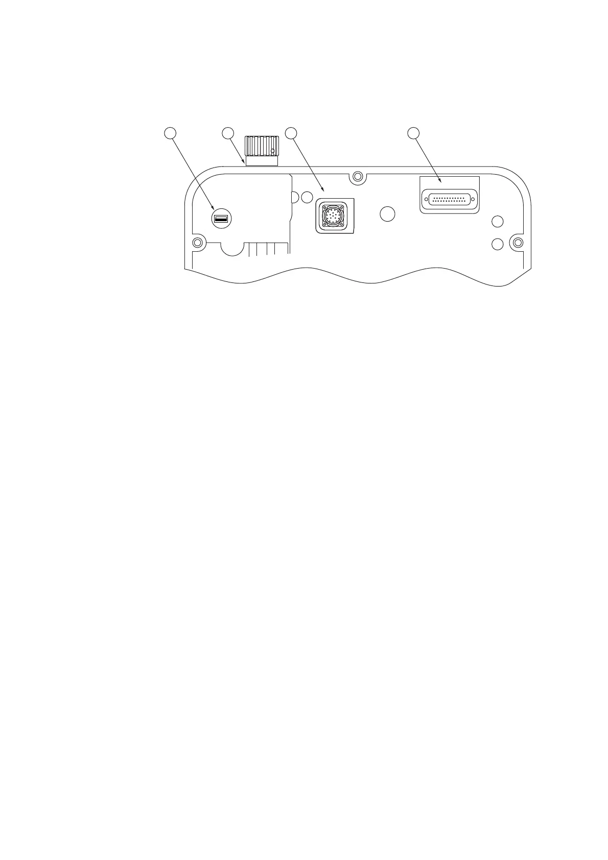
Bottom view
The bottom view of the sensor head (image section) is shown in the following
figure.
Figure 3.3: Bottom view of the sensor head (image section)
1VIDEO
USB interface
Connection for the USB 3.0 cable to the industrial PC to control the video camera
and transmit the video signals.
2
Transport lock
To secure the linear stage to protect the sensor head during transport.
3MOTOR
connection (17-pin circular connection)
Connection for the motor cable from the controller for the power supply and the
signal transmission of the linear stage motor.
4 CONTROL
connection (25-pin Sub-D jack)
Connection for the control cable from the controller for the power supply and the
signal transmission of the linear stage motor.