3-13
3 First Steps
INFORMATION
An optical table board (breadboard) with appropriate dimensions and
designed for the weight (refer to C
HAPTER
5) can be used as a base plate.
1. Place the stand onto the base plate matching up with the drill holes
(slots).
2. Lock the transport lock on the sensor head (refer to F
IGURE
3.2).
3. Place the sensor head on the slots on the stand.
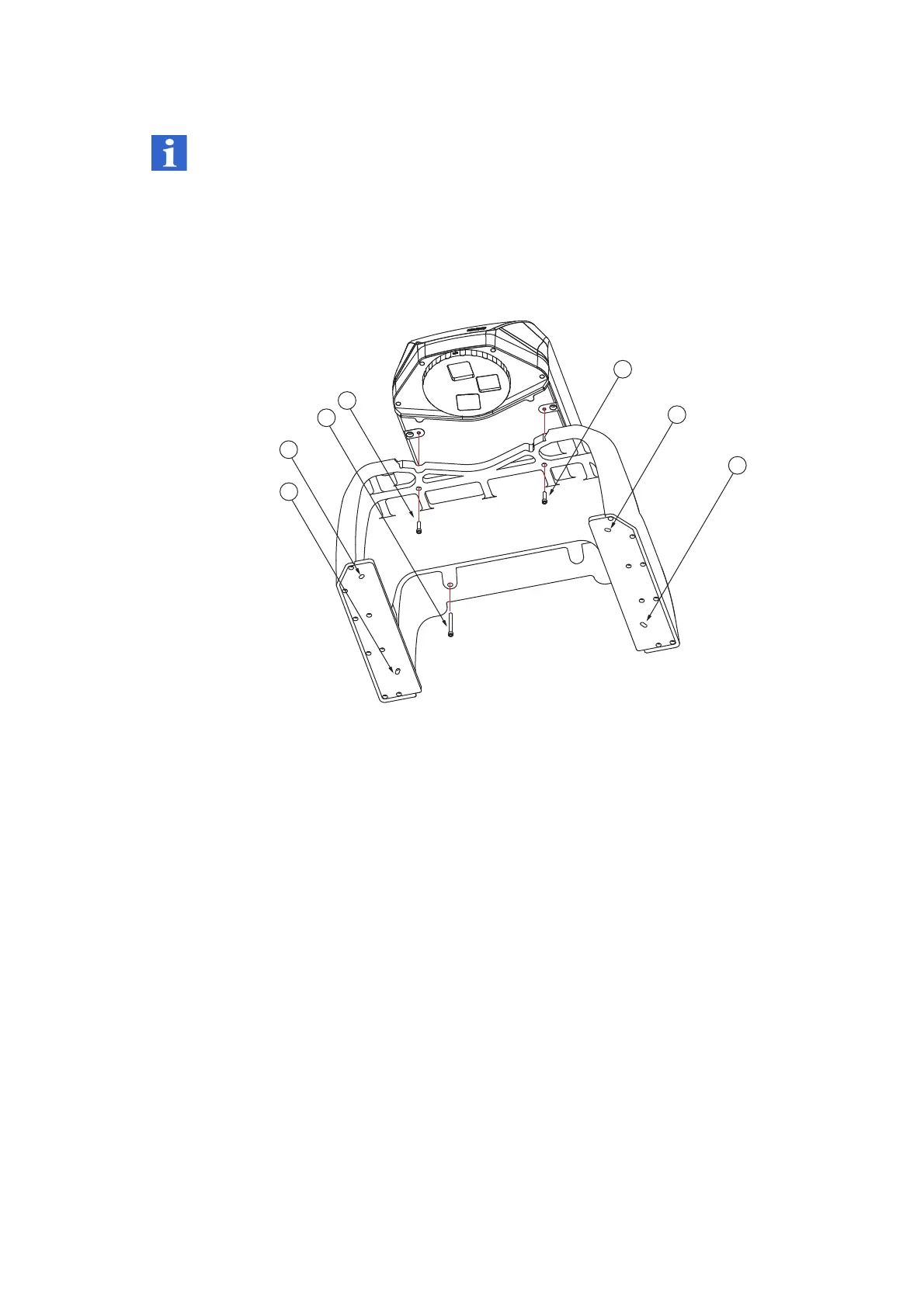
Figure 3.9: Assembling the sensor head on the stand
4. Screw the sensor head onto the stand using the two screws [A] and the
screw [B]. Tighten the screws using a maximum torque of 10 Nm. If you
do not have a torque wrench, tighten the screws hand-tight.
5. Screw the stand onto the base plate using four M6 x 25 or
4 x 1/4"-20UNCx 1" Allen screws and the washers. Tighten the screws
using a maximum torque of 10 Nm. If you do not have a torque wrench,
tighten the screws hand-tight.
6. Unlock the transport lock on the sensor head.
A
2 Allen screws M6 x 25
B
1 Allen screw M6 x 60
C
Slotted holes