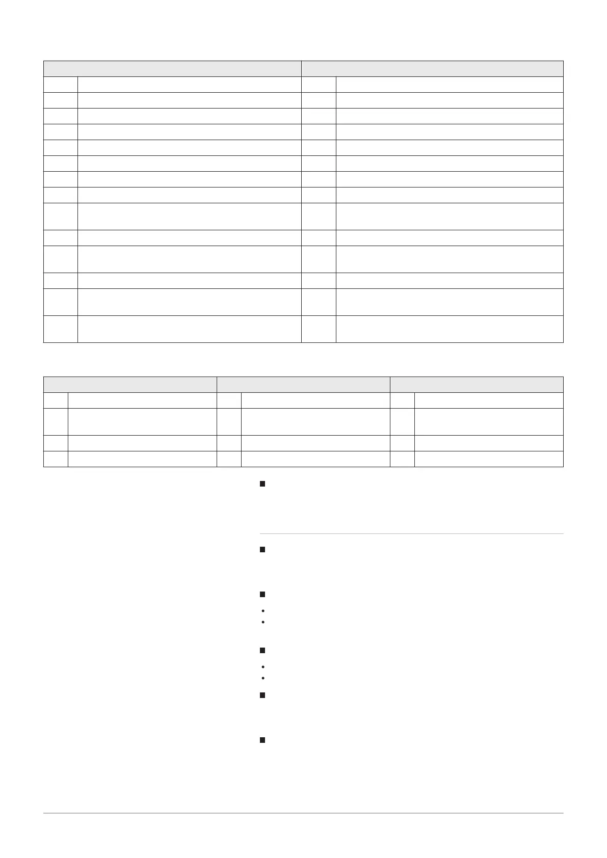
Buffer storage tank Domestic water storage tank
4 Buffer storage tank, heat generation shutoff valve 04 Primary pump
5 Buffer storage tank, solar connection 05 Charging pump, solar connection
Heat gen shutoff valve 13 Diverter valve
14 Diverting valve, solar connection
16 Primary controller, without heat exchanger
17 Primary controller, 1 heat exchanger
19 Intermediate circuit, without heat exchanger
20 Intermediate circuit, 1 heat exchanger
22 Primary pump/intermediate circuit, without heat ex
changer
23 Charging pump/intermediate circuit, 1 heat exchanger
25 Diverting valve, intermediate circuit, without heat ex
changer
26 Diverting valve, intermediate circuit, 1 heat exchanger
28 Primary controller/intermediate circuit, without heat
exchanger
29 Primary controller/intermediate circuit, 1 heat ex
changer
Tab.25 Check no. heating circuit (prog.-no. 6217)
Heating circuit 3 Heating circuit 2 Heating circuit 1
0 No heating circuit 00 No heating circuit 00 No heating circuit
1 DHW circulation via boiler circuit
pump
01 DHW circulation via boiler circuit
pump
01 DHW circulation via boiler circuit
pump
2 Heating circuit pump 02 Heating circuit pump 02 Heating circuit pump
3 Heating circuit pump, mixer 03 Heating circuit pump, mixer 03 Heating circuit pump, mixer
Software version (6220)
Display of the actual software version.
9.2.18 LPB system
Device address (6600) andSegment address (6601)
The two-part LPB address of the controller consists of the 2-digit segment
number and the 2-digit device number.
Bus power supply function (6604)
Off: The controller does not provide the bus power supply.
Automatically: The bus power supply is switched on and off by the con
troller in accordance with the power demand of the bus system.
Bus power supply state (6605)
Off: The bus system power supply by the controller is currently inactive.
On: The bus system power supply by the controller is currently active.
Display system messages (6610)
This setting allows system messages which are transmitted via LPB to be
suppressed on connected operating elements.
Alarm delay (6612)
The transmission of the alarm to the BM module can be delayed in the ba
sic device by an adjustable time. This allows the prevention of unnecessa
ry messages to a service location caused by malfunctions which only oc
cur briefly (e.g. temperature monitor queried, communication errors). How
9 Settings
7658013 - 02 - 15092016 Paramount four 30 – 115 kW 113