Paramount four 30/40 Paramount four 50 - 115
1 Ionization electrode 1 Air vent
2 Ignition electrodes 2 Mixing tube
3 Flame inspection window 3 Ignition and ionization electrode
4 Flow sensor 4 Flame inspection window
5 Air vent 5 Water pressure sensor
6 Mixing tube 6 Siphon
7 Air intake silencer 7 Flue gas adapter with inspection apertures
8 Gas injector 8 Ignition transformer (under the lid)
9 Fan 9 Air intake silencer
10 Pressure sensor 10 Gas jet
11 Siphon 11 Fan
12
DHW charge pump
1)
12 Gas valve
13
Extension module EWM
1)
13
Pump replacement pipe
1)
14 Flue gas adapter 14 Control LMS
15 Inspection openings 15
Extension module EWM
1)
16
Membrane expansion vessel (MAG)
1)
16 Cleaning opening
17 Flue gas pipe 17 Gas pressure monitor
18 Gas valve 1) Accessories
19 Gravity lock
20 Heating circuit pump
21
Connection 2. heating circuit
1)
22 Control LMS
23 Gas pressure monitor
1) Accessories
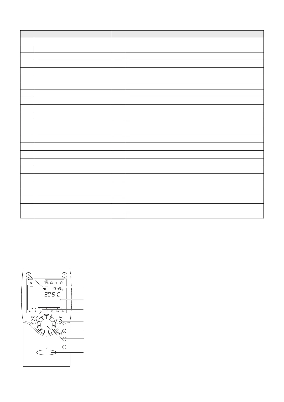
4.1.1 Room device RGT
Remote setting of all adjustable control functions of the basic appliance is
possible via the operating unit when using the room device RGT (accesso
ry).
1 Operating mode key, heating mode
2 Operating mode key domestic water mode
3 Screen
4 ESC key (cancel)
5 OK key (acknowledgement)
6 Presence key
7 Control knob
8 Information key
Presence key
Manual switching over between heating operation at comfort nominal val
ue and heating operation at reduced nominal value is possible with the
presence key, irrespective of the set time programs. The value switched
over to stays active until the next modification by the time program.
Fig.8 Operating interface of the room de
vice RGT
4 Description of the product
26 Paramount four 30 – 115 kW 7658013 - 02 - 15092016