Caution
When the flue pipes are dis-assembled, new seals must be used
for the reassembly!
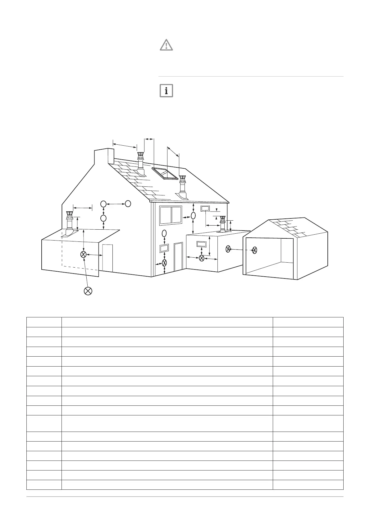
6.3.5 Outlets
Note
When codes of practice dictate the use of a terminal guard use a
suitable guard of stainless steel construction. There must be a
clearance of at least 50 mm between any part of the terminal and
the guard.
Fig.16 Outlets
AD-3000707-01
N
I
I
G
F
M
I
A
A
F
H
J,K
D
E
H
Likely flue positions requiring a flue terminal guard
C
R
A
I
J,K
I
L
S
B
T
U
Tab.12 Terminal position with minimum distance
A
(1)
Directly below an opening, air brick, opening windows, etc. 300 mm
B
(1)
Above an opening, air brick, opening window etc. 300 mm
C
(1)
Horizontally to an opening, air brick, opening window etc. 300 mm
D
(2)
Below gutters, soil pipes or drain pipes. 25 (75) mm
E
(2)
Below eaves. 25 (200) mm
F
(2)
Below balconies or car port roof. 25 (200) mm
G
(2)
From a vertical drain pipe or soil pipe. 25 (150) mm
H
(2)
From an internal or external corner. 25 (300) mm
I Above ground, roof or balcony level. 300 mm
J From a surface or boundary line facing a terminal. 600 mm
K From a terminal facing a terminal (Horizontal flue).
From a terminal facing a terminal (Vertical flue).
1200 mm
600 mm
L From an opening in carport (e.g. door, window) into the dwelling. 1200 mm
M Vertically from a terminal on the same wall. 1500 mm
N Horizontally from a terminal on the same wall. 300 mm
R From adjacent wall to flue (vertical only). 300 mm
S From an adjacent opening window (vertical only). 1000 mm
T Adjacent to windows or openings on pitched and flat roofs. 600 mm
6 Installation
40 Paramount four 30 – 115 kW 7658013 - 02 - 15092016