ing on the heating demand. The pump strives to use the least energy pos
sible to supply the heating circuit.
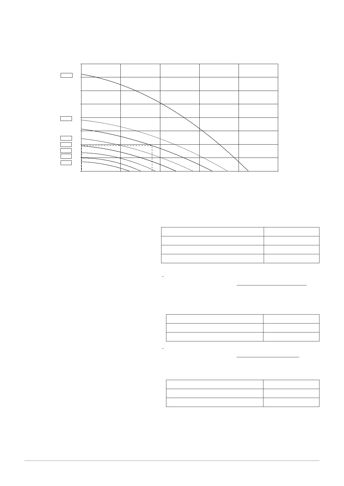
Fig.19 Example of total dynamic head
0
1
2
3
4
5
6
7
8
0 500 1000 1500 2000 2500
Rfh [mWS]
Wms [kg/h]
100%
60%
50%
40%
30%
20%
10%
0%
Rfh Total dynamic head Wms Water mass flow
1. Parameter 883 (Pump speed max)
The max. pump speed results from the design volume flow and the
total dynamic head required at this point (see Fig.).
Tab.18 Example (Fig.)
Design volume flow 900 l/h
System resistance at the design point 19 kPa (1.9 mWS)
=> Max. speed (read off) 50%
=> Set parameter 883 50%
2. Parameter 882 (Pump speed min)
Heating systems with radiators
The minimum pump speed for heating systems with radiators is
the result of entering the system resistance again at volume flow
zero l/h in the diagram (see Fig.)
Tab.19 Example (Fig.)
System resistance at the design point 19 kPa (1.9 mWS)
=> Min. speed (read off) 30%
=> Set parameter 882 30%
Underfloor heating systems
The minimum pump speed for underfloor heating systems results
from 75% of the maximum pump speed.
Tab.20 Example (without illustration)
=> Max. speed (read off) 50%
=> Min. speed (read off) 0.75 * 50% = 37.5%
=> Set parameter 882 37%
8 Operation
7658013 - 02 - 15092016 Paramount four 30 – 115 kW 55