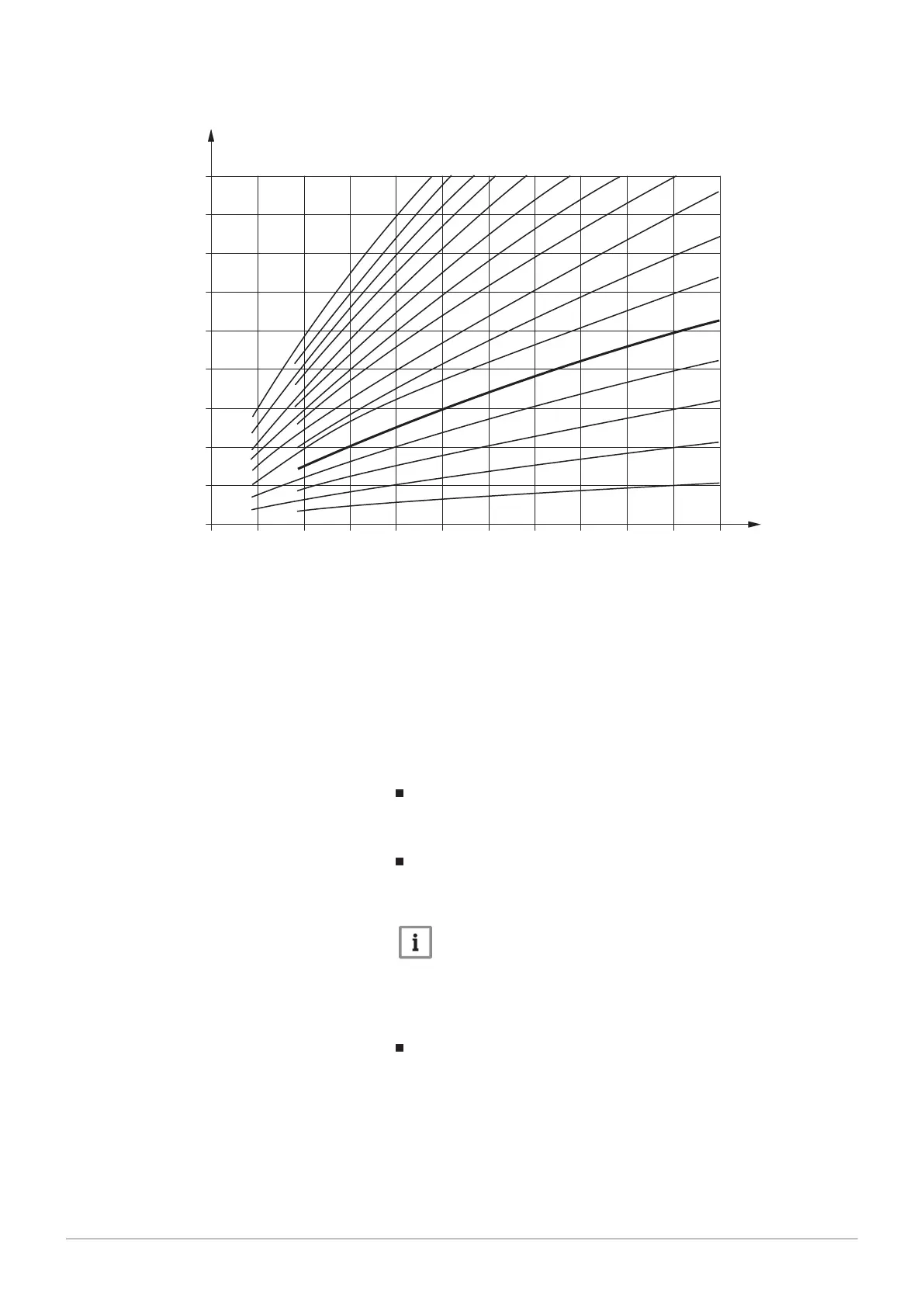
Fig.20 Heating curve diagram
4
3,5
3
2,74
2,5
2,24
2
1,74
1,5
1,24
1
0,76
0,5
0,24
20 10 0 -10 -20 -30 °C
30
40
50
60
70
80
90
100
°C
AT
VT
RA-sRE036B
AT Outdoor temperature VT Flow temperature
Determination of the heating curve gradient
Enter the lowest calculated outside temperature in accordance with the cli
mate zone (e.g. -12 °C in Frankfurt) into the diagram (see fig.) (e.g. verti
cal line at -12°C). Enter the maximum flow temperature of the heating cir
cuit, at which a room temperature of 20 °C is still calculated to be reached
at -12 °C outside temperature (e.g. horizontal line at 60 °C).
The intersection of both lines provides the value for the heating curve
slope.
Heating curve displacement (721, 1021, 1321)
Heating curve correction by parallel offset if the room temperature is gen
erally too high or too low.
Heating curve adaption (726, 1026, 1326)
Automatic adaptation of the heating curve to the actual conditions, as a re
sult of which no correction of the heating curve slope is required.
Note
Automatic adaptation of the heating curve requires the connection
of a room sensor. The value for Room influence (see prog. no.
750, 1050, 1350) must be set between 1% and 99%. Should there
be radiator valves in the lead room (where the room sensor is in
stalled), these must be fully opened.
Summer/winter heating limit (730, 1030, 1330)
9 Settings
84 Paramount four 30 – 115 kW 7658013 - 02 - 15092016