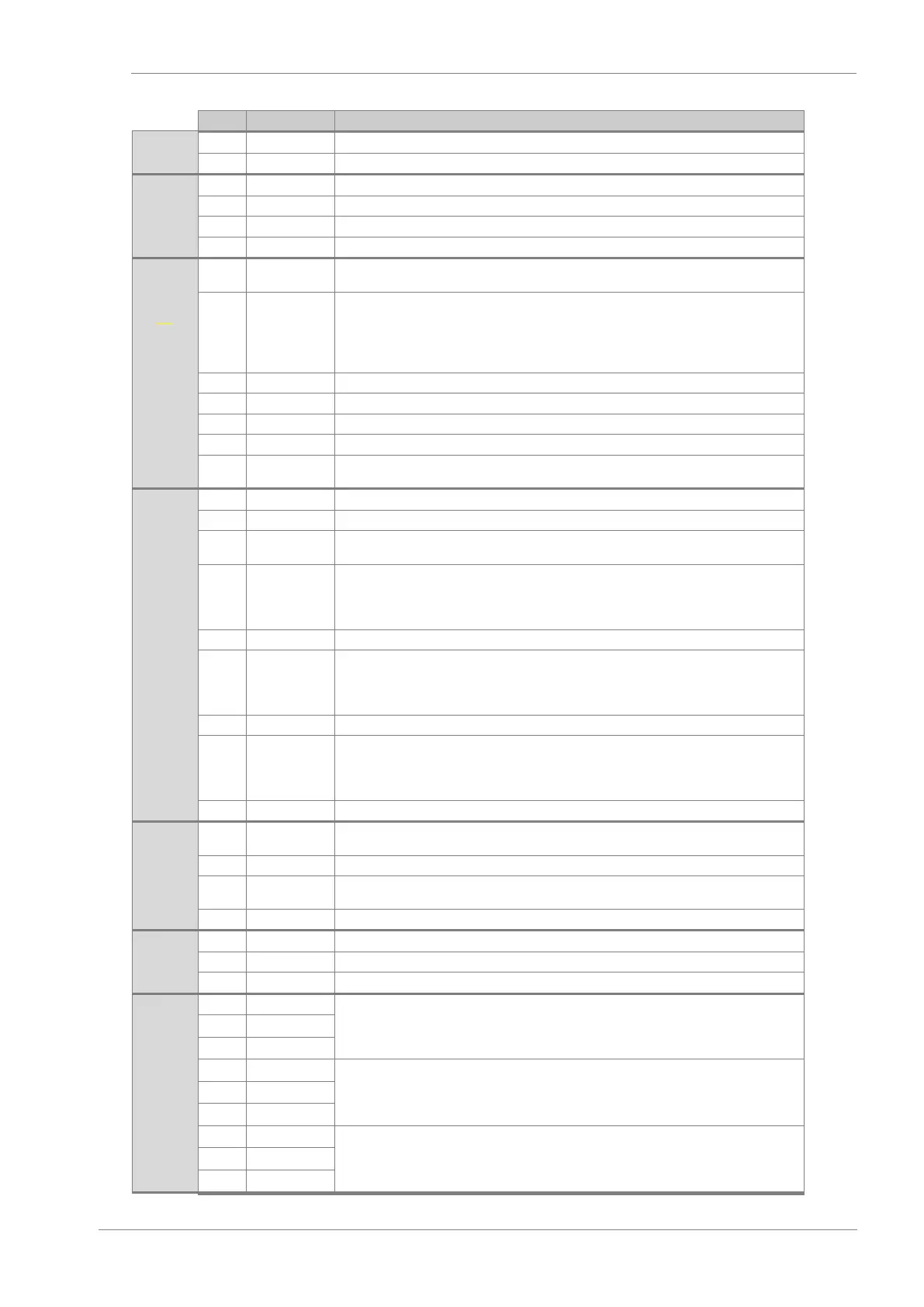
Power supply 24Vdc control card.
Safety common input STO 1.
Safety common input STO 2.
Power supply for digital intputs. Protect against short circuit and overload. (Maximum
+24Vdc, 180mA).
Programmable Digital Input 1 (Digital Input 1). Digital inputs are configured in the Input
group. Their status can be displayed in the visualisation group. It is powered from
terminal 7 or form an external power 24Vdc supply. If an external power supply is used,
the common must be connected to terminal 29 (GND_USER). Programmable input as
PNP and NPN
[2]
.
Programmable Digital Input 2. Same features as DI1.
Programmable Digital Input 3. Same features as DI1.
Programmable Digital Input 4. Same features as DI1.
Programmable Digital Input 5. Same features as DI1.
Programmable Digital Input 6. Same features as DI1. Besides, input configurable as
digital PTC.
GND connection (0 V) for inputs
Supply voltage for analog inputs
10V power supply for potentiometer. Ready to supply a maximum of 2 potentiometers (R
1k).
Voltage or current Programmable Analogue Input 1 (V o mA). Configurable to 0-10Vdc,
0-20mA or 4-20mA
[3]
.
The value of the input resistance in voltage mode is Ri=20kΩ. The value of the input
resistance in current mode is Ri=250Ω.
Voltage or current Programmable Analogue Input 2 (V o mA). Configurable to 0-10Vdc,
0-20mA or 4-20mA.
The value of the input resistance in voltage mode is Ri=20kΩ. The value of the input
resistance in current mode is Ri=250Ω.
Voltage or current Programmable Analogue Input 2 (V o mA). Configurable to 0-10Vdc,
0-20mA or 4-20mA.
The value of the input resistance in voltage mode is Ri=20kΩ. The value of the input
resistance in current mode is Ri=250Ω.
Voltage or current Programmable Analogue Output 1 (V o mA). Configurable to 0-10Vdc,
0-20mA or 4-20mA.
Voltage or current Programmable Analogue Output 2 (V o mA). Configurable to 0-10Vdc,
0-20mA or 4-20mA.
RS485 Modbus serial communication interface.
RS485 Modbus serial communication interface.
Digital Output 1. Programmable change over relay (NO / NC). Potential free (Maximum:
250VAC, 8A; 30VDC, 8A).
Digital Output 2. Programmable change over relay (NO / NC). Potential free (Maximum:
250VAC, 8A; 30VDC, 8A).
Digital Output 3. Programmable change over relay (NO / NC). Potential free (Maximum:
250VAC, 8A; 30VDC, 8A).