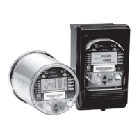
Configuring Front Panel Displays ION 8000 Series User Guide
Page 164 Chapter 15 - Displays
Choose the screen type
Select the parameters available for your chosen screen type
Select your display qualities, including digit resolution and truncated or
rounded last digits.
5. Click Send to save the changes in the meter.
Using Designer
CAUTION
Before you reconfigure or delete a framework, you should make a copy. This ensures that you can restore
the framework without having to reinitialize the factory configuration.
To remove a data display screen:
1. Launch Designer.
2. Select the Display module responsible for the screen.
3. Press delete. This also deletes all links to that particular Display module.
If the display screen you are deleting is part of the automatic scrolling cycle, you
should reconfigure the links from the Scroll module’s Trigger outputs to the
remaining Display modules so that the following considerations hold true:
The first Display module in the scrolling cycle is linked to the Trigger 1 output of
the Scroll module.
The last Display module in the scrolling cycle (module n) is linked to the
Trigger n output of the Scroll module. For example, if your scrolling cycle
consists of 5 screens, then Trigger 5 should be linked to the fifth module in the
cycle.
The Wraparound setup register of the Scroll module designates the last trigger
output (Trigger n). Expanding on the previous example, since Trigger 5 is the last
trigger, the Scroll module’s Wraparound setup register would have a value of 5.
To add a new display screen
1. Create a Display module.
2. Define the modules characteristics (display format) by adjusting its setup
registers.
3. Link any required data to the Source inputs of the Display module.
If you want your new screen to appear in the automatic scrolling cycle, then you
must link the Show input of the Display module to a Trigger output of a Scroll
module.
To create a Disk Simulator screen
1. Create a new Display module, and choose the type as Disk Simulator.
2. Connect the new Display module’s first input to the Calibration Pulser module’s
Disk Position output that you want to monitor for its pulsing interval.

 Loading...