24
PowerBox-Systems − World Leaders in RC Power Supply Systems
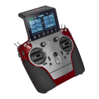
In this example the PBS-V60 voltage sensor is to be used to
reduce motor power if the voltage of the flight battery falls to a
dangerous level. You can rename the telemetry control under
the Name field.
Now locate the field under Output showing the percentage
value and briefly press it in order to set all the parameters. The
following display now shows various possible settings. The
Sim. button can be used to simulate all the settings, avoiding
the need to carry out protracted tests.
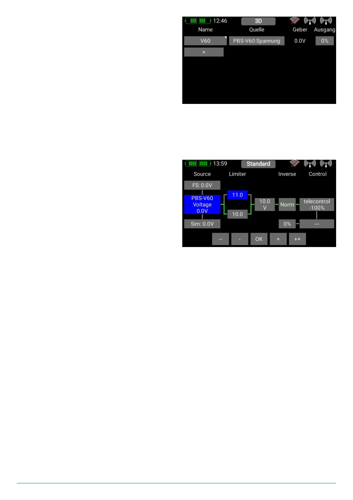
Explanation of the control elements:
3.8.1. Source
Under Source you will see three buttons which you can press
in turn to select the telemetry control input.
• FS
At this point you enter the value which is to be adopted if - for
whatever reason - the telemetry value no longer arrives at the
transmitter. Since you may have set the telemetry control to
operate a safety-relevant function, it is very important to se-
lect at this point a value for that function which is non-critical.
• Source
Here you find the current sensor value, including the name and unit of measurement.
• Sim.
At this point you can see how the output behaves by simulating values using the Plus / Minus buttons. The values which can
be entered here apply to the decimal point of the actual sensor.