6
PowerBox-Systems − World Leaders in RC Power Supply Systems
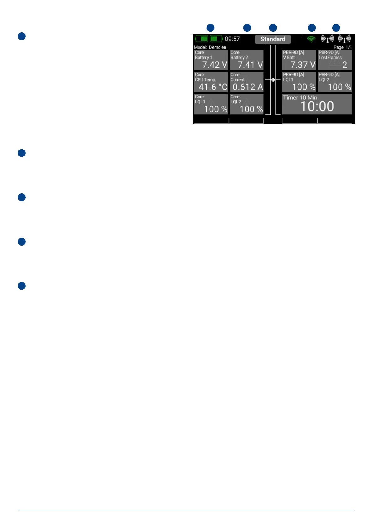
• Main Screen
1
Battery indicator
The two green battery symbols indicate the state of charge
of the two internal batteries. The charge status is divided up
into five blocks, each of which stands for 20% of charge. The
charge symbols change to orange and then red if the state of
charge falls below 20% and 10% respectively. You can also
set up a telemetry widget to display the exact battery voltage.
Setting up a telemetry widget provides the opportunity to add
an audible or spoken alarm.
2
Processor Status
This symbol is displayed when the workload on the Linux computer reaches a particular level. The symbol flashes briefly when
data is being processed.
3
Flight Mode
This field shows the current flight phase (flight mode). The name of the flight phase can be set individually in the Flight Mode
menu.
4
Wifi
This symbol is cancelled with a red line if WiFi is not active. WiFi is only active when it has been switched on manually, or automa-
tically during the Update process.
5
Aerial symbols
The aerial symbols illustrate in graphic form the LQI value of the Atom’s aerials, i.e., it corresponds to the reception quality of the
return channel.
1 2 3 4 5