Page 26 of 49 Instructions/Parts list Multi-Dumper MCE400 updated: 04.2021
Attachment broom (accessory)
The attachment broom is mounted on the front of the frame of the MCE400 using an adapter and
provided with an extra plug. The attachment of the broom is limited to a mechanical and electrical
coupling of the broom and the MCE400. The broom is switched on or off via a button which is installed
in the control box of the broom.
Controller
Status-LEDs
The Curtis series 1226 controller has a red and a yellow status LED. The following table describes
which status of the controller the LEDs describe.
The flashing cycle is 1.5 seconds.
The LED flashes for
500 msec, followed by a delay of 1 sec.
Flashes the first digit of the fault code.
Flashes the second digit of the fault
code.
For details, see the following section.
Display Fault Codes
Fault codes consist of two digits, with the digits delimited by a comma. For example, the Parameter
Change fault’s code is 5,2.
The red status LED shows the fault code’s first digit and the yellow LED shows the second digit. The
fault LEDs’ flash cycle operates as follows:
• The red LED is on for 250ms, followed by a 250ms delay.
• The yellow LED is on for 250ms, followed by a 250ms delay.
• A 2s delay occurs, then the cycle is repeated until the fault is cleared.
If there are multiple active faults, the controller flashes each fault code using the sequence described
above. After fault codes for all active faults have been flashed, an additional 2s follows the last fault
code.
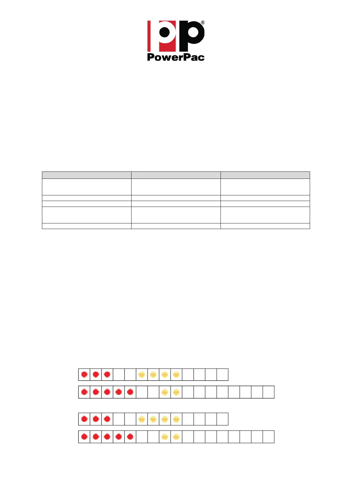
Fig.: 12 shows how the status LEDs flash when for example both, the 3,4 and 5,2, faults are active.
Each block in the diagram represents 500ms.