5.1 Connecting Audio Inputs
5.1.1 Analog Connection
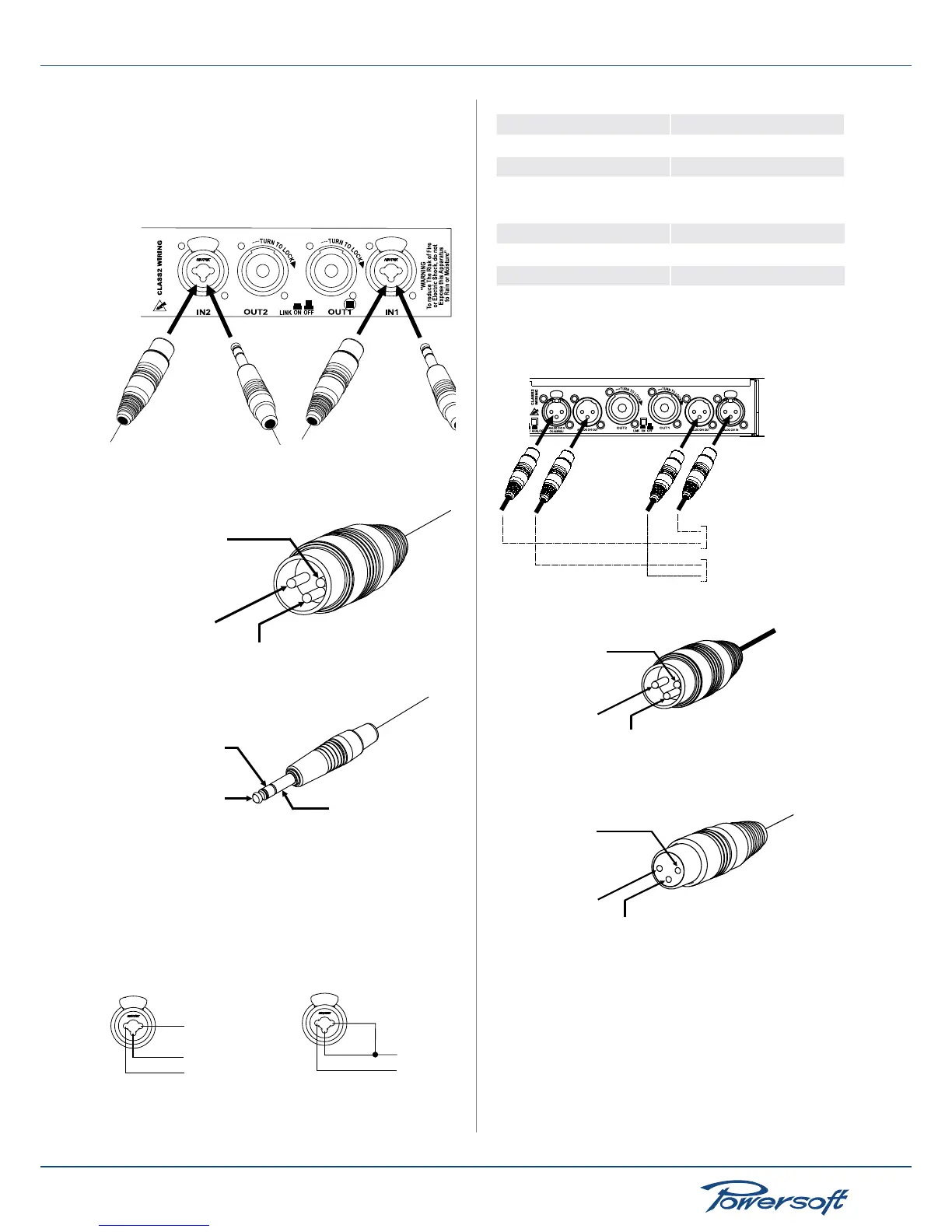
Input connections are made via the 3-pin XLR-female type or
1/4” phone Jack connectors on the rear side of the amplier. The
polarity is shown in the following gures:
FIGURE 11:
Audio input connection for K6/K8/K10/K20 models
FIGURE 12:
pin 2 - IN (+)
pin 1 - shield
pin 3 - IN (-)
ring - IN (-)
sleeve - shield
tip - IN (+)
Audio input connections polarity
The gure below shows the connection of analog inputs for
balanced or unbalanced line. You can use both congurations, but
you must consider that unbalanced and long lines can introduce
noise in the audio system. The “Link On/Off” switch located in
the rear panel is for direct paralleling of the rear input connectors.
The remaining input connectors can be used to carry signal to
other amps.
FIGURE 13:
Balanced input Unbalanced input
IN (+)
IN (+)
IN (-)
shield
shield
Balanced and unbalanced input connections
XLR pinout chart:
XLR Pin number Assigned to
1 shield
2 hot (+)
3 cold (-)
Audio jack pin out summary:
Connector element Assigned to
sleeve shield
tip hot (+)
ring cold (-)
For K3 and K2 models, input connections are shown in the gure
below; analog inputs for balanced and unbalanced lines are also
available for these models.
FIGURE 14:
signal source input
XLR female connector
signal source output
XLR male connector
K2 and K3 models audio input connections
pin 1 - shield
pin 2 - IN (+)
pin 3 - IN (-)
pin 2 - IN (+)
pin 1 - shield
pin 3 - IN (-)
XLR male
XLR female
FIGURE 15: K2 and K3 models audio input connections polarity
5.1.2 AES/EBU Connection
On DSP equipped ampliers, CH2 becomes the AES/EBU input
when the AES/EBU pushbutton is released (see FIGURE 16); in
this mode, if an analog input in CH2 is applied, the ANALOG CH2
OUT is off. If CH2 is to be used as an analog input, the AES/EBU
pushbutton must be pressed.
 Loading...


