8.2.1.5 Cross Limit
In case of power limiting of only one channel, (see “Limiters” on
page 25) the gain reduction on one channel is mirrored to the
other channel in order to maintain consistent levels. This is useful
in two ways speakers where the limitation of one channel alone
leads to an unbalanced sound. This function can be turned on or
off.
8.2.1.6 Sound speed (m/s)
This menu allow the user to set the sound velocity used for time
to distance conversions throughout the local interface. It can be
set from 320 m/s to 360 m/s.
8.2.2 Channel Settings
All of the following settings are available for both channel 1 and
channel 2. In all the following menus and submenus, the channel
number whose properties are being edited is shown in the top
right hand corner of the menu. If a specic parameter affects both
channels, the top right hand corner will report this as “1+2”.
8.2.2.1 EQs
This menu gives access to the parametric output equalizer input
interface. This menu lists the 16 parametric lters one by one.
The current selected lter number is shown on the left of the rst
line. By pressing the up and down pointing arrows, it is possible
to move from one lter to the next. The lter parameters are
reported on the screen.
filter
FIGURE 41: Parametric Equalizer (PEQ) information window
Specically:
▶
Ac tive: determines if the lter is enabled or not (at response)
Gain(dB): lter gain. Can be set only if the lter is a peaking
or shelving lter. Acceptable values go from -15 to +15dBs in
0.1dB steps
▶
Q factor: quality factor of the lter. This can be user set for
all lters except shelving lters. Acceptable values range from
0.1 to 30 with 0.1 steps.
▶
Bandwidth (oct): the bandwidth of the lter expressed in
octaves around the central frequency. This value is the inverse
of the Q factor; therefore, its value is determined by setting
the Q factor.
▶
Type: allows the user to select the lter type:
1. Peaking
2. Low Shelving (3 to 15dB/oct)
3. High Shelving (3 to 15dB/oct)
4. Low pass EQ
5. High pass EQ
6. Bandstop
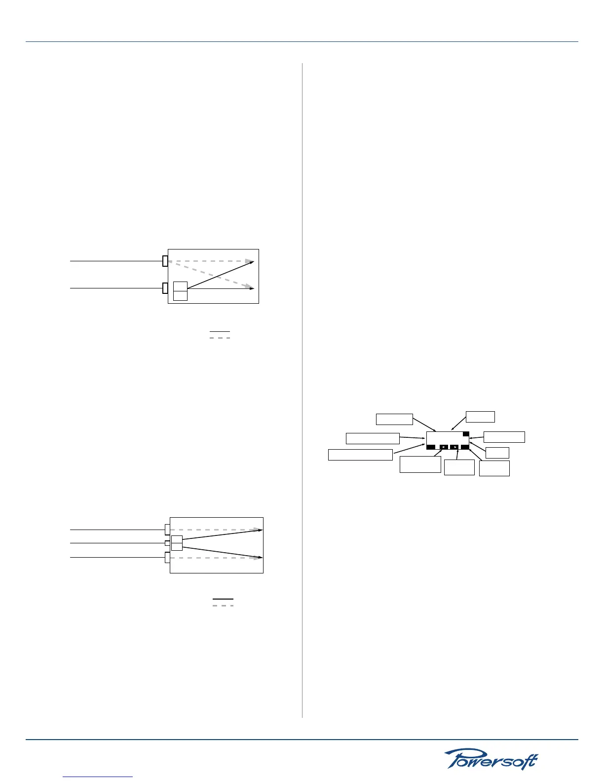
When using the analog input to backup a failed AES3 feed, the
analog input connection must be setup based on source type of
input AES3 stream:
AES3 from rear XLR:
the primary audio signal for this amplier conguration is an AES3
signal, fed via the rear panel IN2 with the rear signal type push
button set to “AES/EBU”. The backup analog cable, with an analog
signal identical to that provided by AES3, should be plugged in the
IN1 (analog) plug. The amplier’s source selection must be set
to “Input from CH1”. If the AES3 feed should fail, the amplier
will automatically fall back to the analog input on the CH1 plug.
The signal levels of both primary AES3 and backup analog signals
should be carefully matched so they are identical. This can be done
using the Gain trim parameter or by adjusting the analog signal
level.
Analog back up cabling
(carrying the same signal as the
CH1 of the AES3 feed)
Digital main cabling
IN1
(analog)
IN2
(AES/EBU)
CH1
CH2
CH1 out
CH2 out
(amplifier in Source Selection
“Parallel from CH1” mode)
main digital connection
analog backup connection
(used if digital fails)
FIGURE 39: Analog back up mode connection: in this example, the
amplier is set to output the AES3 CH1
AES3 from KASEOP:
the primary audio signal for this amplier conguration is an AES3
signal, fed via an Ethernet port. The backup analog cable, with an
analog signal identical to that provided by AES3, should be plugged
in the IN1 (analog) and IN2 (set to analog) plugs. The amplier’s
source selection can be set to any possible input. If the AES3 feed
should fail, the amplier will automatically fall back to the analog
input on the CH1 and CH2 plugs. The signal levels of both primary
AES3 and backup analog signals should be carefully matched so
they are identical. This can be done using the Gain trim parameter
or by adjusting the analog signal level.
Analog back up cabling
(carrying the same signal as the
CH1 of the AES3 feed)
IN1
(analog)
IN2
(analog)
CH1 out
CH2 out
Analog back up cabling
(carrying the same signal as the
CH2 of the AES3 feed)
Main digital AES3 stream via RJ-45
CH1
CH2
main digital connection
analog backup connection
(used if digital fails)
FIGURE 40: Analog back up mode connection: in this example, the
amplier is set to output the AES3 stream in stereo mode. Other
congurations of the amplier mode are possible.
When the AES3 stream is lost and the analog backup kicks in, a
message on the front panel is displayed and an alarm is sent to the
remote client if one is connected to the amplier.
 Loading...


