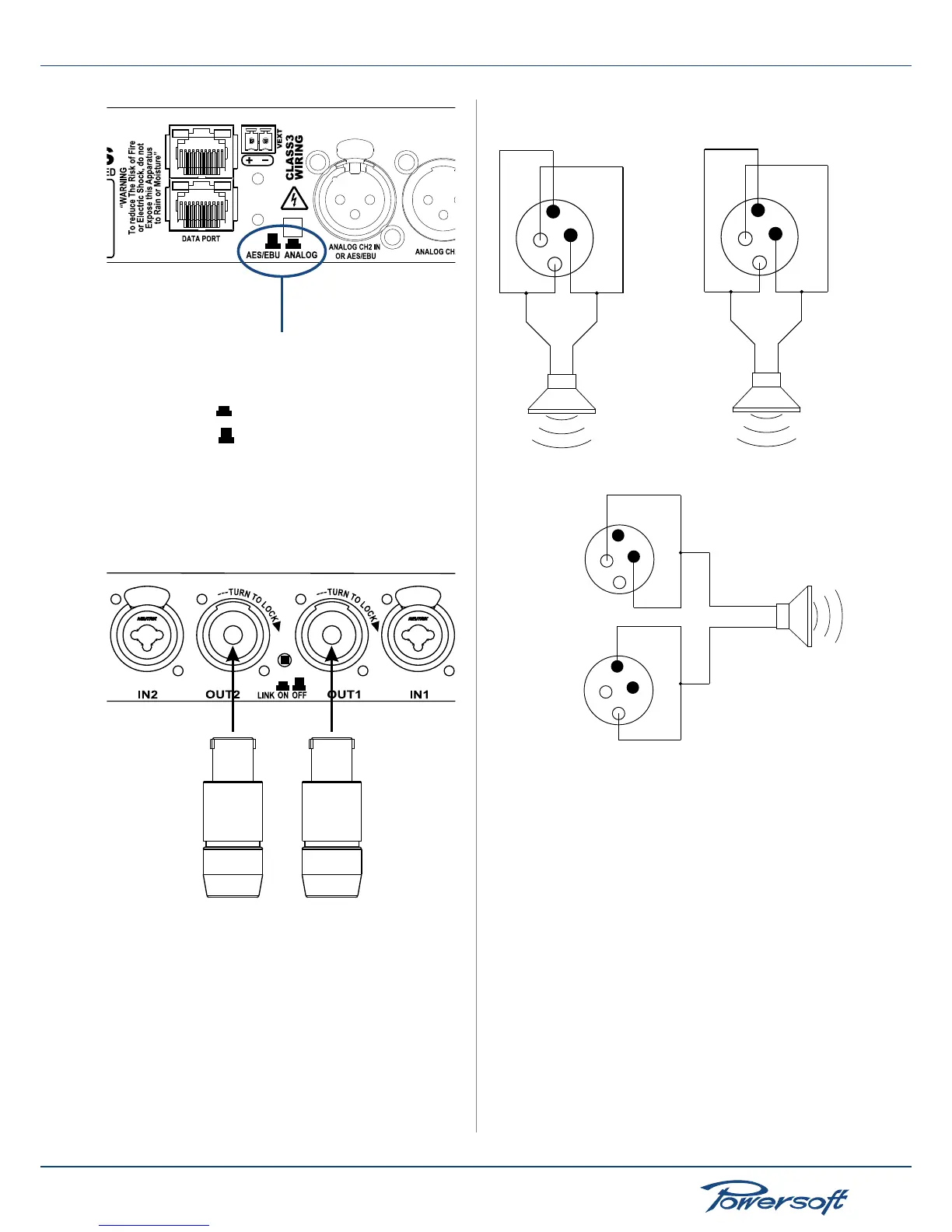
Channel 2 AES/EBU or analog
input selection button
analog input
AES/EBU input
FIGURE 16: AES/EBU or analog input selection for channel 2
5.2 Connecting Audio Outputs
Audio output connections are made via Neutrik® speakon
connectors.
FIGURE 17:
Audio output connector
Use suitable wire gauges to minimize power and damping factor
losses in speaker cables. All K Series amplier outputs can also be
congured to work in bridge mode. For each device, the 1+ and
2+ pins of speakon connectors are internally physically bridged
together. They are the positive pole of the channel output. Pins
1- and 2- are also bridged together. They form the negative pole
of the channel output. Please note that in order to remain within
safe operating conditions, when using loads of 4 � or less (8 � or
less in bridge mode),connections must be made with a four wire
cable. Use one cable for each SpeakOn contact for either bridge
or stereo connections as shown in the following gures.
FIGURE 18:
1 -
1+
2+
2-
+
-
OUT1
1 -
1+
2+
2-
+
-
OUT2
Audio output connection in stereo mode
1 -
1+
2+
2-
+
-
OUT1
1 -
1+
2+
2-
OUT2
FIGURE 19: Audio output connection in bridge mode
5.3 Internal Signal Path Polarity
In order to increase the power’s supply energy storage efciency,
signals coming from channels 1 and 2 are polarity reversed one
with respect to the other when entering the amplier. This
ensures a symmetrical use of the voltage rails: if, for example,
both channels’ 1 and 2 input signals are going through a peak at
the same time, channel 1’s energy will come from the positive
voltage rails while channel 2, whose polarity is reversed with
respect to channel 1, will be fed energy from the negative voltage
rails. In this manner, the power supply will work symmetrically,
with one channel catered by the positive rails and the other by
the symmetrical negative rails. Channel 2’s signal will be polarity
reversed once more to ensure that both channels output with the
same polarity as their corresponding input signals. For this reason
it is very important not to invert the polarity of either channels
before feeding them to a K Series amplier. A double polarity
inversion (the rst by the user inserting the input signal and the
other by the amplier’s internal circuitry) results in no inversion at
all. If this were the case, both channels would be weighing on only
 Loading...


