one side (positive or negative) of the power supply’s voltage rails.
This would result in an inefcient use of the power supply’s energy.
FIGURE 20:
first polarity
inversion
second polarity
inversion
Channel 1
input
Channel 2
input
Channel 1
output
Channel 2
output
Internal signal path polarity with example input signals.
Both channels 1 and 2 are fed the same sine signal
Please pay special attention in using balanced inputs on all
measurement equipment (such as oscilloscope probes) when
you are bench testing.
5.4 Remote Control Connection
5.4.1 V Ext
The “V Ext” terminal is used to remotely turn on, turn off or
put in standy any K Series amplier. The “V Ext” signal reaches
the amplier via pin 2 of the rear Ethernet connector for 2 port
models. Four port models have a dedicated 2 pin Phoenix port
located near the rear Ethernet ports. When the V ext port is
powered by and external 12 VDC 1A power supply, an internal
controller is enabled to listen for incoming device power-on/off/
standby commands.
CLASS2
WIRING
FIGURE 21: Vext Phoenix connector in 4 port K Series ampliers
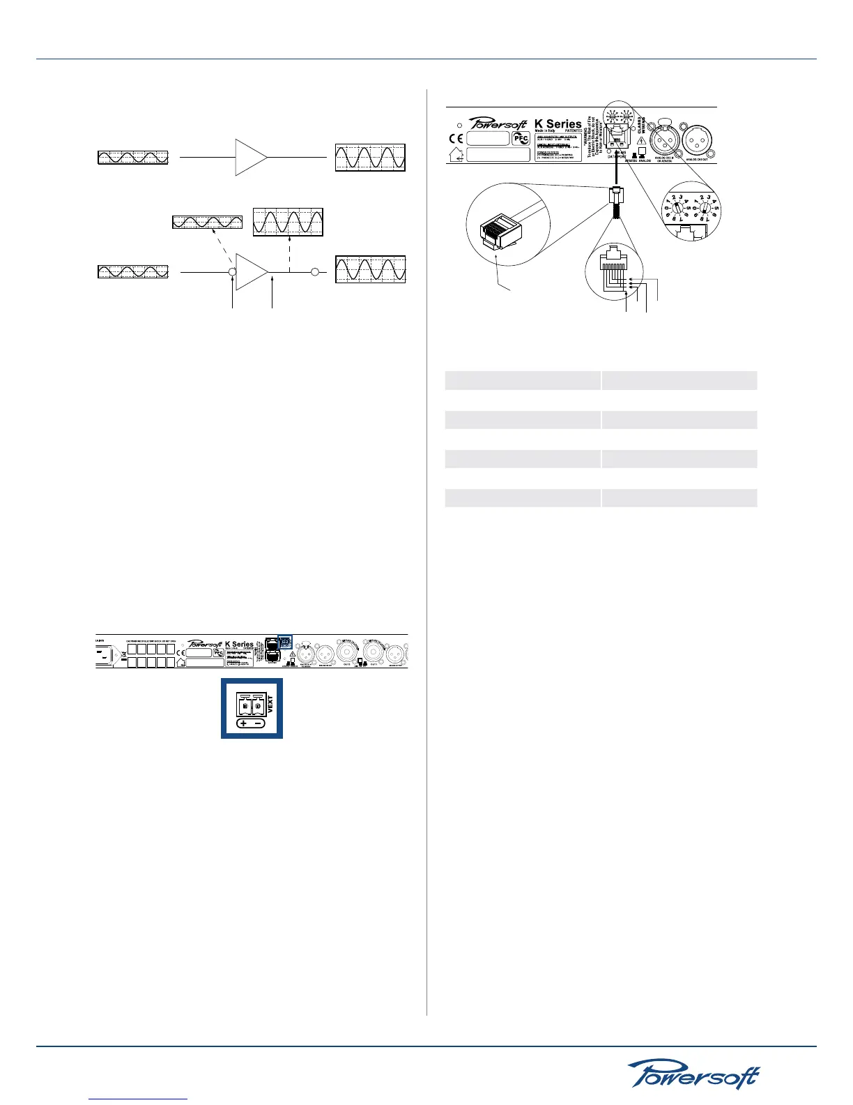
5.4.2 Serial Connection
K Series ampliers without an optional KAESOP board can be
remotely controlled via an RS485 connection. Remote connection
data cables must have an 8 pin modular plug to be inserted in the
RJ45 jack labelled “DATAPORT” on the rear of the amplier. By
plugging an 8 pin modular plug and selecting the unit’s remote
ID via the rotary trimmers, the amp is ready to be remotely
controlled. Please note that ID numer 00 is not allowed.See
FIGURE 22 for details.
FIGURE 22:
ID selection example
ID = 28
GND
485-
485+
Vext
Pin Layout
8 pin
modular
plug
Remote connection jack, plug and ID selection
Remote connection jack pinout chart:
1 GND
2 Vext
3 485 -
4 485 +
5 485 +
6 485 -
7 Vext
8 GND
5.4.3 Ethernet Connection
K Series ampliers can be remotely controlled via an Ethernet
connection if provided with a KAESOP board. Two- or four-
ports ampliers allow Ethernet data connections with a variety
of possible topographies. See “9 Network Operations” on page
29 for more details. If four plugs are present (two in the front
and two in the back of the amp), the pair in the back are master
ports, while the two in front are slave ports.
 Loading...


