7 Amplier Settings
7.1 Output attenuation
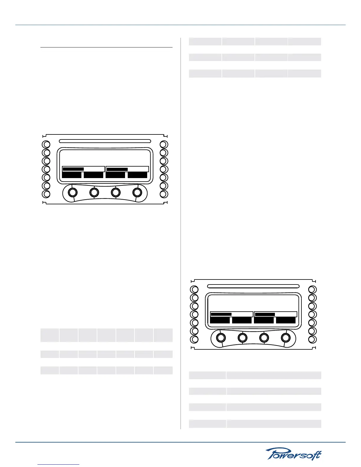
The output attenuation screen sets the amplier’s output
attenuation level. The user can choose whether to set output
attenuation for channel 1, channel 2 or both by cycling through the
right most button. The “+” and “-” buttons change the value of the
output attenuation in the range from 0 to -30dB. A single “+” or
“-” button press will increase or decrease the output attenuation
by 1dB. Note: for ideal sonic performance, select a 0dB output
attenuation (meaning no attenuation), and select the proper
gain/sensitivity level as explained in the next paragraph.
Output attenuation
back C1+2
-
+
-13 -13dB
FIGURE 30: K Series output attenuation
7.2 Input Gain/Sensitivity
All K Series ampliers allow selection of input sensitivity to allow
correct sensitivity matching with other third party equipment.
The user can choose whether to set the input gain/sensitivity for
channel 1, channel 2 or both by cycling through the right most
button. The “+” and “-” buttons change the value of the input gain
and corresponding sensitivity. The allowed gain values are 26dB,
29dB, 32dB and 35dB. The table below shows the input sensitivity
values for the K Series ampliers. These are the maximum RMS
voltage values of an input 1kHz sine wave before clipping occurs at
the output stage. These values are reported with respect to the
amplier’s gain.
K Series gain sensitivity. Input signal: 1kHz sine wave. Voltage
values are RMS:
Gain
(dB)
K2 K3 K6 K8 K10 K20
26 4.48 5.30 5.11 5.50 6.34 7.37
29 3.17 3.75 3.62 3.90 4.49 5.22
32 2.47 2.66 2.56 2.75 3.18 3.68
35 1.59 1.88 1.81 1.95 2.25 2.62
The maximum balanced input signal before saturation of the input
stage of the amplier occurs with respect to the amplier’s gain is
presented in the chart below. Input signal: 1kHz sine wave. Voltage
values are RMS:
Gain (dB) dBV dBu V
RMS
26 25.0 27 18
29 21.6 24 12
32 19.0 21 9
35 15.6 18 6
7.3 Input select
K Series ampliers allow the user to choose three different input
modes (if available): Analog, AES3
1 and/or 2
, and KAESOP
2
. Each of
these inputs can either be processed by the internal DSP or not.
The up and down buttons on the “Input select” screen toggle
between the available input sources. The “sel” button locks the
selected option.
The possible input/signal path congurations are:
▶
Analog ==> Out (analog input and direct output)
▶
Analog ==> DSP ==> Out
1
(analog input and internal DSP
processing, output)
▶
AES3 ==> Out
1 and/or 2
(AES3 input, direct output)
▶
AES3 ==> DSP ==> Out
1 and/or 2
(AES3 input, internal DSP
processing, output)
▶
KAESOP ==> Out
2
(AES3 input, direct output)
▶
KAESOP ==>DSP==>Out
1 and 2
(KAESOP input, internal
DSP processing, output)
1
Available only with optional DSP board
2
Available only with optional KAESOP board
7.4 Max output voltage
The max output peak voltage of K series ampliers can be set
by the user. It is possible to set output peak voltage levels for
channel 1, channel 2 or both by pressing the “C1+2” button. The
“+” and “-” buttons change the value of the max output peak
voltage.
Max output voltage
back - +
C1+2
102 102Vpeak
FIGURE 31: Max output voltage settings screen
The ranges available are shown in the table below:
Amplier model Peak output voltage (V)
K2 40 to 140
K3 40 to 165
K6 40 to 153
K8 40 to 169
K10 40 to 200
K20 40 to 225
 Loading...


