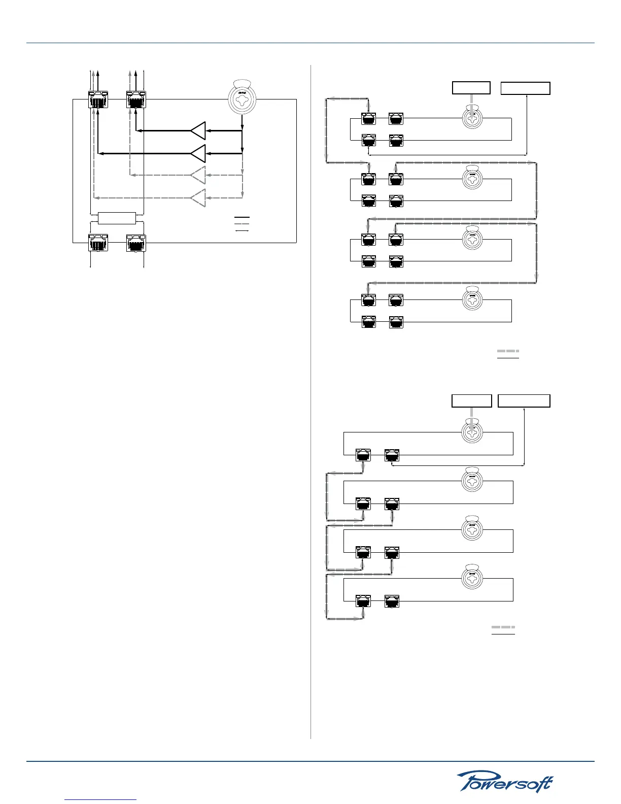
FIGURE 51: AES3 stream coming from the rear XLR stream is routed
to both AES3 streams A and B via the master RJ45 ports.
IMPORTANT: when an amplier is set to forward the XLR AES3
signal to either the AES3-A or AES3-B stream, the amplier can
accept as the sole AES3 input signal the one coming from the
XLR connector. The RJ45 ports cannot, when the amplier is in
forwarding mode on both streams, input an AES3 signal to the
amplier.
9.2 Network robustness
K series ampliers equipped with a KAESOP are capable of
being connected each to the other via a network: using a single
sound source, each amplier in the network can be, for example,
dedicated to providing power audio signal to a given subsection
of a large venue. In dealing with networks of ampliers, one of
the most important aspects to consider, especially when working
in a critical application such as large venue sound distribution, is
the robustness of the network itself. Data and audio connections
can be made “fault proof”: this means that if for some reason
one audio or data connection should fail, the whole system is not
compromised. The degree of redundancy expresses how many
network connections can break before sound is interrupted in
any one amplier part of the system. A “zero degree” redundant
system is not robust: the rst connection to jump (either from a
cable failure or even from an amplier problem) means the whole
system goes down. A “one degree” redundancy system, on the
other hand, will continue working automatically if one (but no
more than one) connection fails. This happens because K series
ampliers can sense a connection failure and automatically (and
almost instantaneously) invert the audio feed direction to allow
the source signal to remain uninterrupted.
The following section illustrates and analyzes some common
amplier networks divided by redundancy degrees.
9.3 Network connections
▶
Daisy chain
The following diagrams show a daisy chain connection of 4
ampliers.
FIGURE 52: Daisy chain connection of four ampliers with four RJ45
ports each
Ethernet networkAES3 source
Port 1
(master)
Port 2
(master)
Device mode: forward to AES3-A
Port 1
(master)
Port 2
(master)
Device mode: repeat
Port 1
(master)
Port 2
(master)
Device mode: repeat
Port 1
(master)
Port 2
(master)
Device mode: repeat
AES3-A
Ethernet
FIGURE 53: Daisy chain connection of four ampliers with two frontal
RJ45 ports each
The rst amplier in the chain receives the AES3 input from the
rear panel XLR connector and then forwards it to the AES3-A
(or, alternatively, the AES3-B) stream. In order to do so, the rst
amplier mode is set to “forward to AES3-A stream”. Instructions
on how to set the amplier mode can be found in section “10.1
Device Mode” on page 36. The second amplier in the chain
 Loading...


