ZeroConf).
The amplier behavior complies with RFC 3927, guaranteeing the
interoperability with any host PC supporting this standard.
10.3 Set Address
This menu allows to manually set the amplier’s IP address, subnet
mask and default gateway.
10.4 Show Net Cong
This menu shows the current networking conguration, either set
by the user via the “Set address” menu or obtained automatically
if the automatic addressing mode is selected.
10.5 Audio
10.5.1 Source Selection
This menu allows the user to select the AES3 stream source to
feed the output power stage of the amplier. The AES3 signal can
come from either:
▶
AES3 XLR: the rear panel XLR connector, while the “AES/
EBU-Analog” pushbutton is in the “EAS/EBU” selected
position
▶
AES3-A: the AES3-A stream coming from one of the two
master RJ45 ports (either the two in the back of the amplier
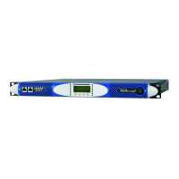
for 4-port amps, or the two in front for amps with only two
RJ45 jacks)
▶
AES3-B: the AES3-B stream coming from on of the two
master RJ45 ports (either the two in the back of the amplier
for 4-port amps, or the two in front for amps with only two
RJ45 jacks)
10.5.2 Source Mode
This menu allows to selects the channel(s) contained the selected
AES stream to be forwarded to the output power stage of the
amplier. The possibilities are:
▶
Parallel from L: the left channel from the selected AES3
stream (see “8.2.1.1 Source Selection” on page 22) is
forwarded to both amplier channels
▶
Parallel from R: the right channel from the selected AES3
stream (see “8.2.1.1 Source Selection” on page 22) is
forwarded to both amplier channels
▶
Stereo: the right channel from the selected AES3 stream goes
to channel 1 or the amplier; the right channel from the AES3
stream goes to the amplier’s left channel.
10.5.3 Gain Trim
This parameter trims the digital level of the AES3 stream. The gain
trim scale goes from +5dB to -40dB with 0.5dB steps. The 0dB
gain trim level has an analog level equivalent of +13.5dBu. A 0dBFS
level in the AES3 stream corresponds to an absolute analog level
of +18.5dBu (with a +5dB gain trim level).
Note: please note that when using a digital input, the amplier
will keep a xed 32dB gain.
10.5.4 If no link
This parameter allows the user to choose the behavior of the
amplier when the digital audio stream is missing and the Input
Selection is set as KAESOP=>OUT. The two possible alternatives
are:
▶
Mute: in this case the amplier output is muted
▶
Analog: in this case the amplier automatically switches
to CH1/CH2 analog input if the digital stream is missing,
returning to the digital stream in case this should become
available again. This mode could be used to implement an
analog backup connection for the digital stream.
11 Display
11.1 Output Meters
The output meters screen shows important output signal
information for the amplier. By pressing the right most front
panel button, the screen view is toggled between information
relative to channel 1, channel 2 or relative to the sum of channels
1 and 2
1
The top line in this screen displays the RMS voltage value
of the output, both as a number as well as a horizontal meter
bar. The second and third line display the output RMS current
and power level respectively. The output power reported is a
peak value reading taken every 200 ms. The bottom line of the
screen displays the load impedance as “Zload”. The minimum
output voltage is stored internally and available to remote clients
connected to the amplier. The load impedance is indirectly
inferred by a successive approximations. Time between single
output impedance approximations depends on the output
signal: the greater the amplitude of the signal, the shorter the
time interval between measurements needed to approximate
the output impedance, the faster the successive approximation
method will converge to the true impedance value.
back
Zload=8.0 C1+2
70 Vrms
9 Arms
630 Watt
FIGURE 62: Output meters screen for a bridged channel 1/channel 2
connection. Measured load impedance in this example is 8 Ohms.
11. 2 Temperature
This screen displays the current amplier temperature.
1Note: in the “C1+2” mode, the RMS voltage and power readings
displayed are the average RMS voltage and peak power of each
channel. The RMS current value, on the other hand, is the sum of
each single channel’s RMS current level.

 Loading...
