V
peak
=
R
Where R is the nominal impedance of only ONE driver, P
peak
is the peak power and V
peak
is the peak output voltage. A peak
limiter, used with a very rapid onset (i.e., with a very short attack
time), can also be useful in limiting the maximum peak voltage in
distributed constant voltage lines.
Powersoft designed the K Series limiters as protective measures;
therefore, they are not meant to “color” the sounds such as
dynamic compressors can do. With this in mind, time constants
for these limiters should be selected so as to limit potentially
harmful phenomena which persist for no more than one or two
periods of the related signal bandwidth. To limit the dangers of
dangerous very fast transient signals, all limiters implement a look
ahead time of 0.5s.
The following table gives a few examples of attack and release
times with respect to the frequency range of the signal to be
limited:
FREQUENCY
RANGE (Hz)
AT TACK
TIME (ms)
AT TACK /
RELEASE
R ATIO
RELEASE
TIME (ms)
<63 45 x16 720
63-125 16 x16 256
125-250 8 x8 128
250-500 4 x8 32
500 -1k 2 x4 8
>1k 1 x2 2
The peak limiter menu allows the user to dene the following
parameters:
▶
Active: toggles the power limiter’s on/off status
▶
Threshold (V
pk
): the peak voltage threshold at which the gain
begins to be reduced
▶
Attack: the attack time,i.e. the response time of the limiter
intervention
▶
Release: the decay time, i.e. the time constant after which
the limiter’s action is released and the gain restored to the
nominal value.
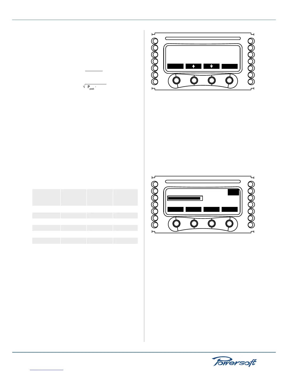
Active:ON
back sel
Thresh.(Vpk):169
Attack(ms):10
CH1
FIGURE 42: Peak limiter main screen
In order to avoid choking the exceptional dynamic range offered
by K Series ampliers, the peak limiter is designed to ignore signal
peaks lasting less than the attack time parameter. Moreover,
the limiter has an additional lookahead buffer to soften clipping
and minimize distortion, effectively yielding superior sonic
performance. The lookahead time is 0.5 ms.
When tweaking the peak limiter’s levels, it is preferable to rst
setup the time parameters, and then adjust the threshold voltage.
When editing the threshold value, the display shows the gain
reduction (GR) in dBs enforced by the limiter. This information,
together with the limiting voltage referred to the signal in the input
amplier stage (I) expressed in dBus, is displayed in real time to
allow monitoring of the limiting actions as they are performed.
Thresh.(Vpk)
ok
fast
- +
169 Vpk
CH1
GR= 0.0dB I= 11.7dBu
FIGURE 43: Peak limiter threshold value editing screen
RMS Limiter
Given the low efciency of electromechanical transducers, almost
50% of power reaching the voice coil is transformed into heat. The
power limiter is intended to avoid melting the voice coils of drivers
while at the same time exploiting their maximum performance. All
the power limiter base their operations on the temporal behavior
of the voltage and the current, this means that the amplier can
knows the real amount of real power delivered to the load. A
correct power limiting is not an easy task and is multifaceted, based
on a number of variable, like the knowledge of the component heat
dissipation and the goals that must be achieved. Therefore may be
difcult and a little bit empirical decide thresholds and constants
time. Power limiters behavior base their operations on a mix based
on threshold, temporal behavior of the output readings (voltage
and/or current) and the type of output readings monitored. The
power limiter should be used to protect the drivers from melting.
It should NOT be engaged at normal working levels. Check the
gain reduction: in order to obtain the optimal sound it should
 Loading...


