not be greater than 2-4dB even for the loudest piece of music.
Please note that a common musical signal has very high peaks, but
a rather small average level (high crest factor). A continuous tone
has a much higher average power even if it “sounds” less loud
to the human ear. This must be taken into account while setting
up limiter parameters. The power limiter acts by decreasing the
amplier’s gain in order to reduce the power delivered to the load.
There are three main operating modes for the K Series power
limiters.
TruePower
TM
In the TruePower operating mode, the amplier’s active output
power is estimated by measuring the load current. The TruePower
limiter is a Powersoft patent technology useful to avoid overheating
of the voice coil; it can however also be used to avoid power
compression. The amplier’s DSP provides the measurement of
the real power delivered (and then dissipated) to the coil, not the
apparent power handled by the line.
Empirical observation yields the following equation:
P
AES
P
max diss
=
3
where P
AES
is the declared AES Power and P
max diss
is the maximum
power the speaker can dissipate “in real life”.
If the P
AES
is not available, the P
RMS
(declared maximum RMS
power the loudspeaker can handle) can be used; however, it is
important to proceed with caution in evaluating how the P
RMS
value is obtained. If no other values are declared, this rule of the
thumb can be used: the P
AES
can be estimated as 6dB below the
peak power (¼ of the peak power). It is very important to note
that, contrary to what happens with the peak limiter, setting the
TruePower limiter parameters must take into account the number
of speakers connected to the amplier. This is due to the fact
that the real power is calculated not only with the output voltage
(which is identical for all speakers connected in parallel) but also
with the output current (which changes according to the number
of parallel speakers).
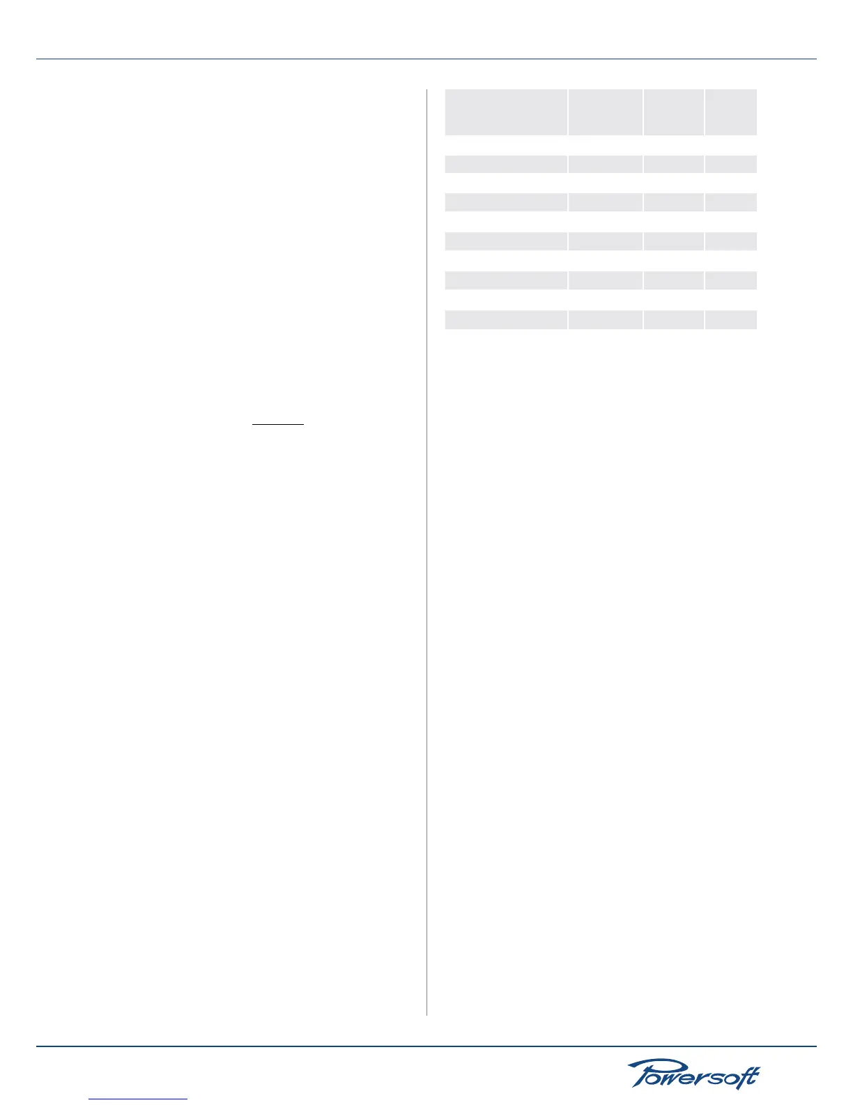
Determining the ideal time parameters for TruePower limiters is a
very empirical process. As a guide, consider this simple rule:
Larger the coil, larger the thermal inertia, larger the time constant.
The following table summarizes this concept with practical
numbers:
Driver voice coil size
(inches) and application
True Power
Threshold
(W)
Attack
time (ms)
Decay
time
(ms)
1” tweeter 10 - 20 100 300
1.5” tweeter 20 - 30 150 300
2” horn driver 20 - 40 200 400
3” horn driver 30 - 50 300 500
4” horn driver 40 - 60 500 3000
2” midrange 30 - 100 500 3000
3” midbass 50 - 150 1000 5000
4” woofer 100 - 200 2000 5000
4” woofer 150 - 250 4000 8000
6” woofer 250 - 500 6000 10000
Power vs V @ 8 Ohm
In the Power vs V @ 8 Ohm operating mode, the amplier’s output
power is estimated by measuring the RMS value of the output
voltage, assuming an 8 ohm load. This mode allows to create
settings that work well for any number of speakers connected
in parallel. For example, if a “Power @ 8 Ohm” limiter is set to
limit the output power to 150W, a single cabinet will be delivered
a maximum of 150W with 8 ohm load. Two speaker cabinets
connected in parallel will be delivered a maximum of 300W with
4 ohm load (“ 8 Ohm loads in parallel) and so on.
This limiter is a pure RMS limiter whose functioning is based
solely on the voltage module measured at the amplier output.
Differently from the TruePower limiter, this limiter does not
take into account the real part of the power; however, it has the
advantage of being independent from the number of cabinets
linked together, just as a peak limiter.
Some attention is needed to set the power threshold. The P
AES
can
be used if it is available. If no other power rating is declared, the
P
RMS
can be used; however, the RMS parameter is a value related
to the maximum manageable power and not the real power.
Proceed with caution because the manageable power could be
greater than the real power. Some constructors declare the RMS
power as the minimum impedance point of the speaker; this,
again, may lead to an overestimation of the true power values the
speaker can handle. If no other values this rule of the thumb can
be used: the P
RMS
can be estimated as 6dB below the peak power
(¼ of the peak power).
In order to preserve the driver in the long term, once the maximum
power limit is decided upon, consider a power reduction of up to
3dB of that value.
In order to use this limiter correctly, it is important to recalculate
the equivalent power at 8 Ω.
For example:
with an 8 Ω speaker with maximum RMS power of 500W, the
threshold power limit is straightforward because the max RMS
power is already given with respect to an 8 Ω load. But if, for
example, the maximum RMS power is 500W for a 4 Ω speaker,
the equivalent power at 8 Ω needs to be calculated.
 Loading...


