receives the AES3-A stream from the master port number 1. Set
in repeater mode, this amplier relays the AES3-A signal to the
third amplier in the chain via the RJ45 port number 2. This setup
is repeated until the nal amplier in the chain receives its AES3-A
signal. The rst connection to the Ethernet network is done via
a CAT-5 cable inserted in any free RJ45 port ( FIGURE 53 shows
port number 3 being used, but ports 2 or 4 could have been used
instead. In FIGURE 54 the only free port is port number 2). The
control data stream, travelling using the Ethernet standard, travels
within the chain alongside the AES3-A stream in a bidirectional
manner.
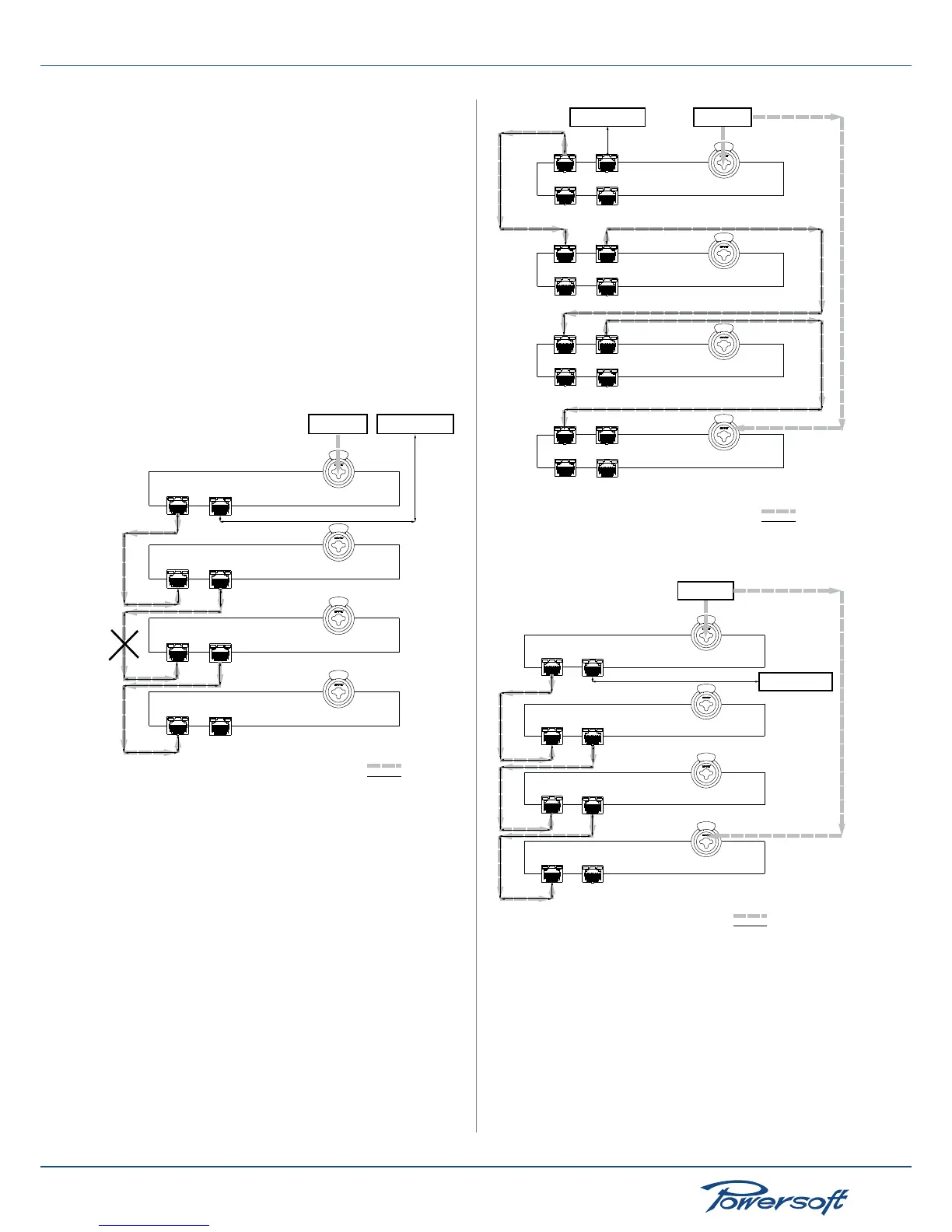
The daisy chain topology is not robust. If any single AES3 or
Ethernet cable connection is interrupted, the whole system fails.
In the diagram below, if the crossed out connection should fail,
both ampliers number 3 as well as 4 would not be able to receive
any audio signal to play. Their connection to the Ethernet network
would fail as well.
FIGURE 54: Daisy chain connection of four ampliers with two frontal
RJ45 ports each: case of internal connection failure between amps
number 2 and 3
▶
Intermediate audio robust chain
A slightly more robust network with respect to the audio system
is the one illustrated in the following diagram. In this connection,
two ampliers, the rst and the last one in the network, are set to
work in forward mode. The remaining “central ampliers” are set
to work in repeater mode.
Port 1
(master)
Port 2
(master)
Port 3
(slave)
Port 4
(slave)
Port 1
(master)
Port 2
(master)
Port 3
(slave)
Port 4
(slave)
Port 1
(master)
Port 2
(master)
Port 3
(slave)
Port 4
(slave)
Port 1
(master)
Port 2
(master)
Port 3
(slave)
Port 4
(slave)
Ethernet network
Device mode: forward to AES3-A
Device mode: repeat
Device mode: repeat
Device mode: forward to AES3-A
AES3 source
AES3-A
Ethernet
FIGURE 55: Intermediate connection, internally robust with respect to
the AES3 stream. Four-port-amplier diagram
Ethernet network
AES3 source
Port 1
(master)
Port 2
(master)
Device mode: forward to AES3-A
Port 1
(master)
Port 2
(master)
Device mode: repeat
Port 1
(master)
Port 2
(master)
Device mode: repeat
Port 1
(master)
Port 2
(master)
Device mode: forward to AES3-A
AES3-A
Ethernet
FIGURE 56: Intermediate connection, internally robust with respect to
the AES3 stream. Two-port-amplier diagram
The fourth amplier’s audio input is the AES3 stream coming from
the XLR connector because it is in forward mode; the AES3-A
stream coming from amplier number 3 via master port 1 is
redundant, meaning it is not necessary for the fourth amplier to
produce sound. The reason for this connection is to improve the
robustness of the audio connection of ampliers 2 and 3.
The system’s connections could be interrupted in the following
ways:
 Loading...


