Installation Setup
13
Powerware
®
9170
+
UPS User’s Guide S Rev B www.powerware.com
3. Carefully replace the UPS cabinet top cover and secure with the
four screws removed in Step 1. Position the cover lip to fit
behind the front panel display.
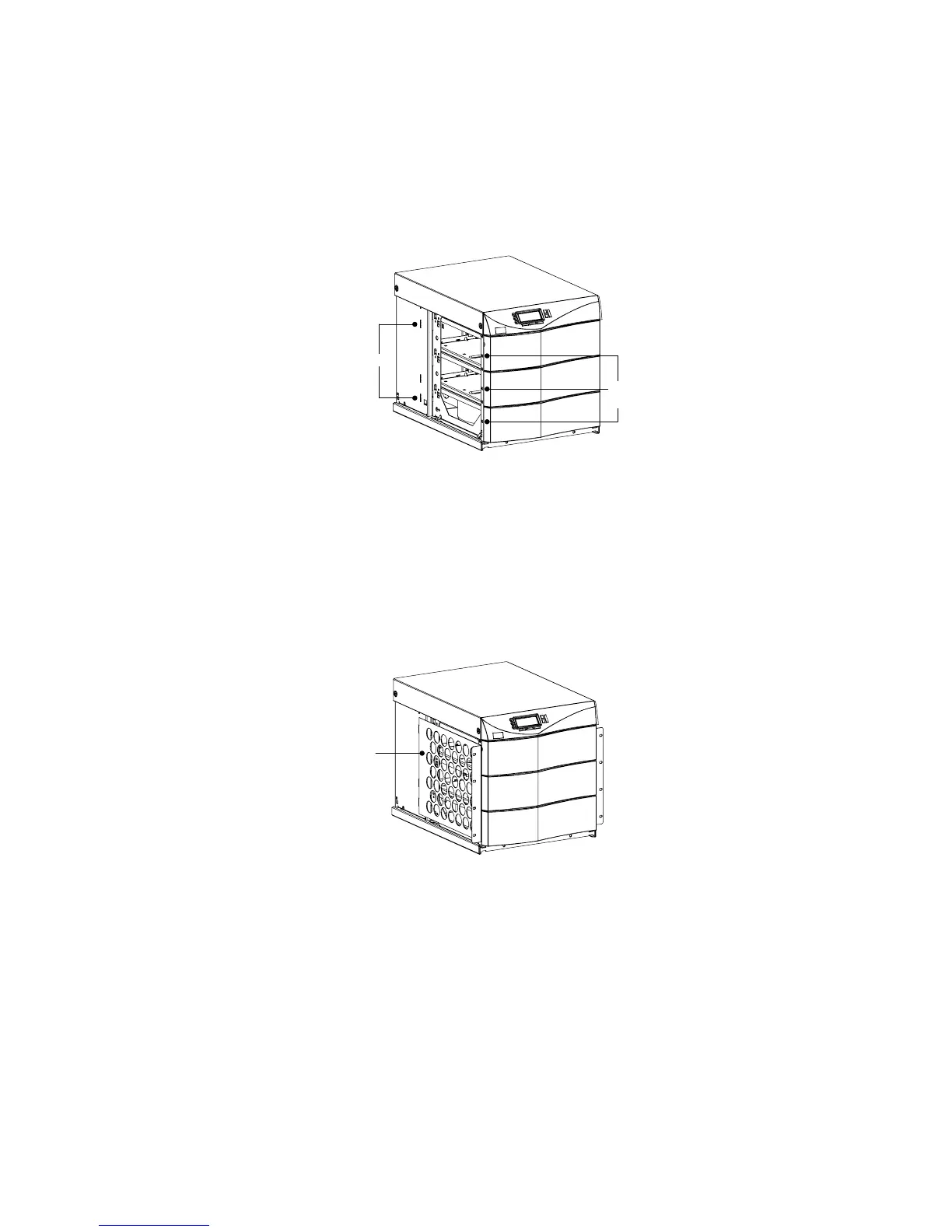
4. Install three metal clip-nuts onto each side flange (6 clip-nuts on
6-slot cabinets) along the front of the UPS cabinet (see
Figure 9).
Tab Slots
Metal
Clip-Nuts
Figure 9. Metal Clip-Nut and Tab Slot Locations
5. Install a rack-mount ear (2 f or 6-slot cabinets) on each side of
theUPScabinet(seeFigure10).
Insert the two offset tabs on the rear edge of the ear into the
matching tab slots on the cabinet side frame (see Figure 9).
Pivot the ear forward until it is flush against the UPS cabinet
side frame. Using three 1/4-20×1/2I Phillips-head bolts, screw
the bolts into the metal clip-nuts installed in Step 4.
Rack-Mount Ear
Figure 10. Rack-Mount Ear Installed