Installation Setup
12
Powerware
®
9170
+
UPS User’s Guide S Rev B www.powerware.com
NOTE If the floor is uneven and the cabinet is tilted or unstable, you may
need to place a thin steel plate under a corner. Do not use the caster
bolts to level the cabinet.
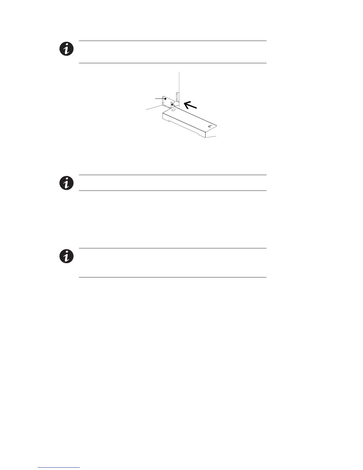
Stabilizer Bracket
Figure 8. Stabilizer Bracket Installation
Rack-Mount Installation (Three- and Six-Slot Cabinet)
NOTE For nine- and 12-slot cabinets, follow the installation instructions
with the nine- and 12-slot rack-mount kit.
The 3- and 6-slot UPS cabinets may be installed in an EIA-standard 19I
(48.3-cm) equipment rack. An optional rack-mounting kit (ASY-0547),
containing brackets and required hardware, is available for such an
installation. For each 3-slot section, use the following mounting
procedure to convert the UPS cabinet and install it in the equipment
rack:
NOTE The UPS cabinet is heavy (see page 102). This procedure requires
two people to lift and position the cabinet into the equipment rack. Install
the cabinet in the rack before installing power and battery modules and
before making connections to the intended power source.
1. Remove the four screws (two on either side) securing the top
cover of the UPS cabinet. Carefully lift the cover straight up and
off to avoid stressing the front panel display. Set the cover
aside.
2. Removethetwocabinetsidepanels(4panelsin6-slotcabinets)
by lifting the top edge. No other hardware must be detached.
Storeordiscardthesidepanels.