Isolated Output Wiring Diagrams
52
Powerware
®
9170
+
UPS User’s Guide S Rev B www.powerware.com
100, 110,
115, or 120
X2
50 or 60 Hz
100/200, 110/220, 115/230, or 120/240V Out
with Isolated Output Option
Parameter 4-2-4 set to 200, 220, 230, or 240, as required.
X1 X3
XX
N-G Bond
L2N
X
L1
200, 220, 230, or 240
100, 110,
115, or 120
X0
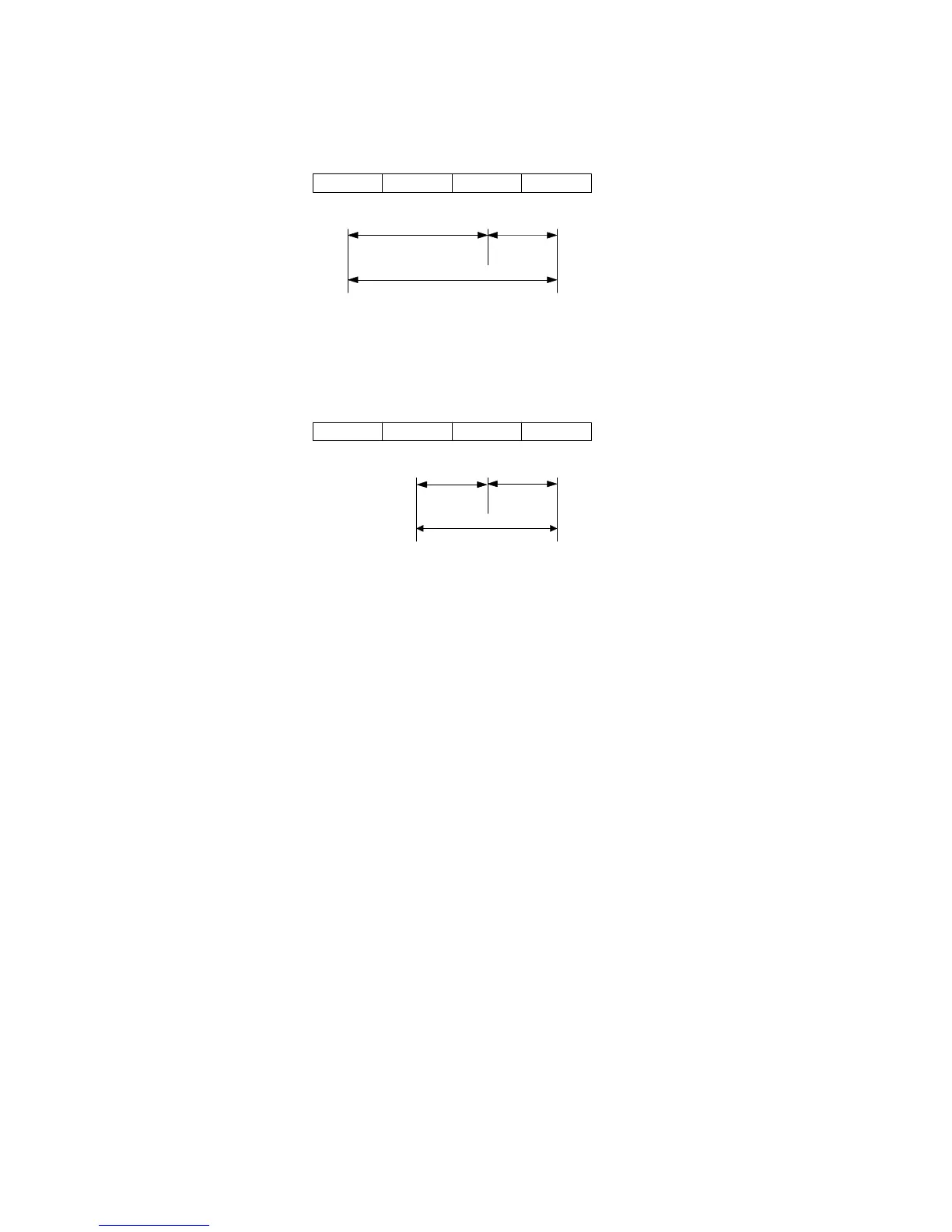
Figure 35. Isolated Outputs – Single-Phase Voltages
X2
50 or 60 Hz
120/208 or 127/220V Out
with Isolated Output Option
Parameter 4-2-4 set to 208 or 220, as required.
X1 X3
XX
N-G Bond
L2N
X
L1
208 or 220
120 or 127
X0
88 or 93
Figure 36. Isolated Outputs – Derived 3-Phase Voltages
Neutral-to-Ground Bonding for Isolated Output
As required under safety regulations issued by various regulatory
agencies, the UPS cabinet must have a ground-bond connection for the
neutral terminal of an isolated-output system. In such a system, the
customer must make the neutral-to-ground (also referred to as N-G or
neutral-to-earth) connection after selecting the desired output
configuration.