Isolated Output Wiring Diagrams
53
Powerware
®
9170
+
UPS User’s Guide S Rev B www.powerware.com
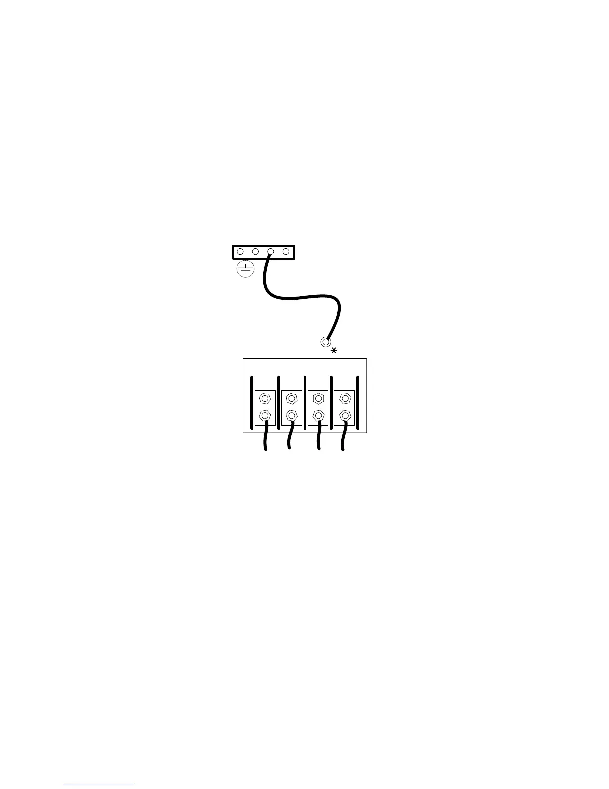
In isolated-output systems, connect the neutral -to -ground
(neutral-to-earth) wire to the proper terminal before making any other
connections to the UPS
. A green and yellow neutral-to-ground bonding
wire is supplied, with one end connected to the ground (earth) UPS
terminal as shown in Figure 37. The other end of the wire (as shown by *
in Figure 37) must be attached to the proper output neutral terminal, as
specified in Figure 35 and Figure 36.
Ground terminations, inside the UPS rear panel, are located directly
below the line input terminals. Figure 17 on page 28 shows input and
output wiring terminals inside the Powerware 9170
+
UPS cabinet.
If there is any question as to the need for this bond wire, contact your
local regulatory agency or your service representative.
N-G Bond Wire
X1 X3 X0 X2
Figure 37. N-G Bond Wire