UPS Electrical Installation
41
Powerware
®
9170
+
UPS User’s Guide S Rev B www.powerware.com
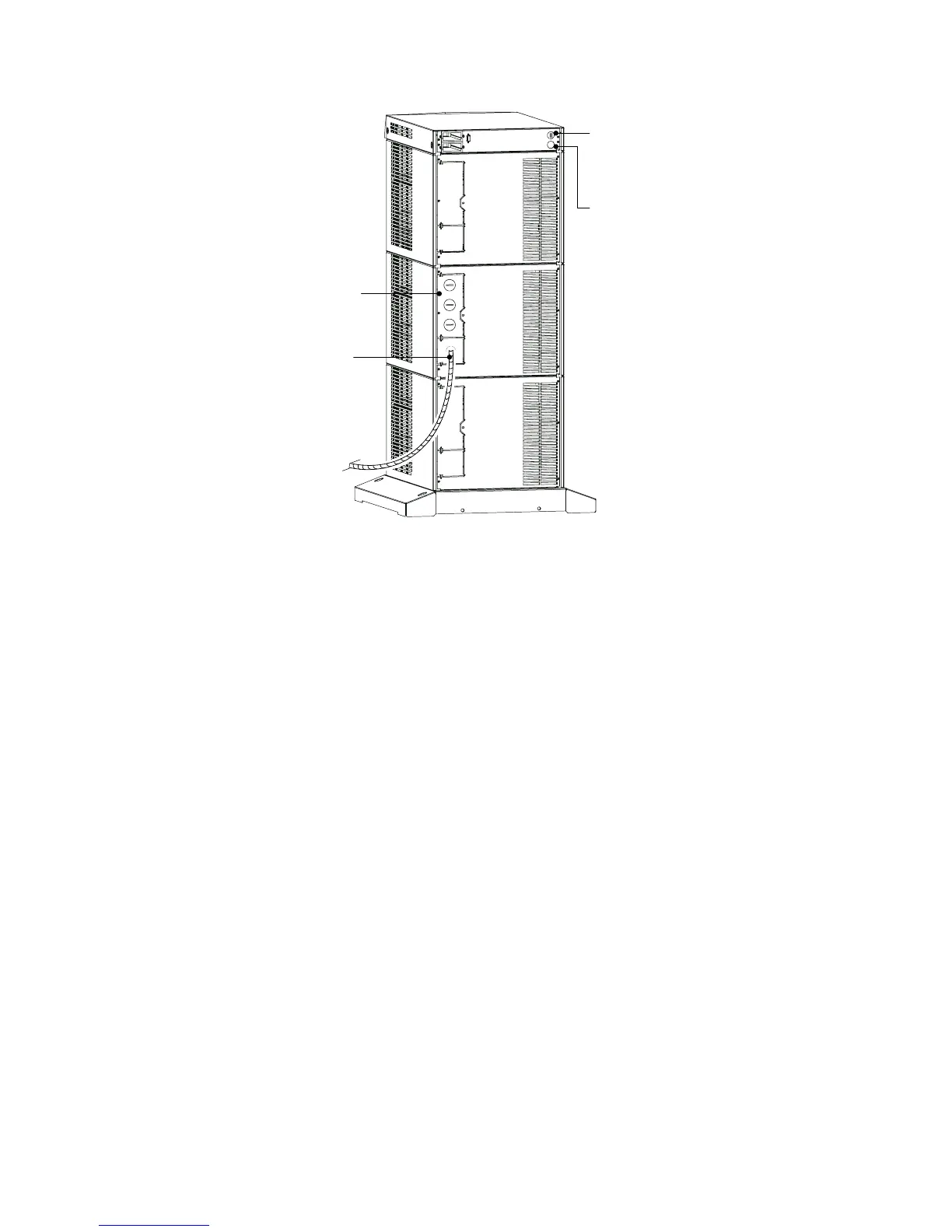
Entrance Panel
Battery Cable
Wiring Access Hole
for Optional EPO
Wiring Access Hole
for an Optional
Generator Input
Signal
Figure 26. UPS Power Entrance Panel (Nine -Slot Cabinet Shown)
2. Remove the knockouts in the entrance panel for AC input and
AC output wiring.
3. Install the conduit adapters. AC input and AC output conductors
must be run through separate conduits. UPS output circuits
must be installed in dedicated conduit systems and not shared
with other electrical circuits.
4. Torque the screws holding all input and output p ower
conductors to the values s pecified in Table 7 on page 39.