TURNING RADIUS
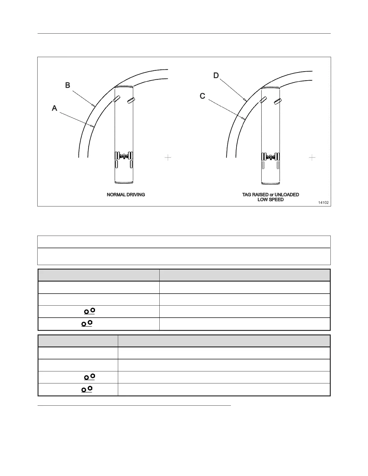
FIGURE 4: TURNING RADIUS DIAGRAM
Table below shows the turning radius values. Values A and B are for normal driving. Values C and D show
values for low speed maneuvering where the tag axle is raised or unloaded .
NOTE
Supplied values are theoretical. Factors such as ground surface, vehicle speed and road conditions may
significantly affect the turning radius.
Turning Radius
1
,
2
H3-45 w/ I-beam Axle
A (Curb to Curb) 41'4" 12.61m
B (Wall to Wall) 45'5" 13.84m
C (Curb to Curb)
39'7" 12.05m
D (Wall to Wall)
43'7" 13.28m
Turning Radius
3
,
4
H3-45, H3-45 VIP with Front Independent Suspension
A (Curb to Curb) 11.34m (37'3")
B (Wall to Wall) 12.64m (41'6")
C (Curb to Curb)
10.84m (35'7")
D (Wall to Wall)
12.13m (39'10")
1
Curb to Curb value corresponds to the outer tire's track on the ground.
2
Wall to Wall value includes the vehicle's body overhang.
3
Curb to Curb value corresponds to the outer tire's track on the ground.
4
Wall to Wall value includes the vehicle's body overhang.
PA-1652 Operator's Manual H3-45 Coach
Technical Information 9-9

 Loading...


