4-20 Controls and Instruments
PA-1652 Operator's Manual H3-45 Coach
WARNING
CoPilot NAVIGATION APPLICATION
DISCLAIMER
Upon delivery from the factory, the H3-45 has
the following vehicle profile characteristics set
in the CoPilot GPS Software System:
Lenght: 45 feet
Width: 107 inches
Height: 151 inches
The operator [user] must always make sure that
the information listed in the CoPilot GPS
Software System’s vehicle profile
characteristics accurately reflects the vehicle’s
dimensions, including a reasonable safety
height margin of 3 inches.
It is the responsibility of the operator to set or
modify the CoPilot GPS Software System
profile characteristics without delay in the event
of any change in vehicle dimensions, such as,
but not limited to:
- Modifications to the vehicle
configuration or dimensions;
- Addition or removal of
equipment, in particular the roof;
or
- Malfunction, rebooting or
updating of the CoPilot GPS
Software System.
The manufacturer shall not be liable for any
damages arising from the misuse of the CoPilot
GPS Software System or from inaccurate
inputs of vehicle dimensions in the system’s
vehicle profile characteristics.
It is the sole responsibility of the operator to
select and drive routes that are compatible with
and safe for the vehicle’s dimensions.
NOTE
Using the microphone while driving is not
recommended. For this reason, there are no
microphones installed on the radio at the
factory.
NOTE
The driver speakers are controlled from the
dashboard radio volume knob while the
passenger’s area speakers are controlled from
the VSS06 Sound Selector volume knob.
HVAC CONTROL UNIT
The vehicle is slightly pressurized by the central
HVAC system to prevent dust and moisture from
entering.
Separate driver and passenger heating,
ventilation and air conditioning controls are
located on this panel. To operate, the engine
must be running.
The driver HVAC unit turns on automatically at
engine start and uses the settings that were kept
in memory before turning off of the system. The
A/C compressor starts automatically when the
two following conditions are satisfied:
1. The outside temperature is above 32 °F (0 °C).
2. The passenger's area temperature has reached 7
°F (4 °C) under the set point.
FIGURE 17: CONTROL UNIT FOR HIGH CAPACITY
CENTRAL HVAC SYSTEM
1) Driver temperature set point adjustment
Increases or decreases the
temperature set point for the
driver’s area.
2) Driver section display
Displays the temperature set point,
the fan speed, the air selection and
recirculate air status for the driver

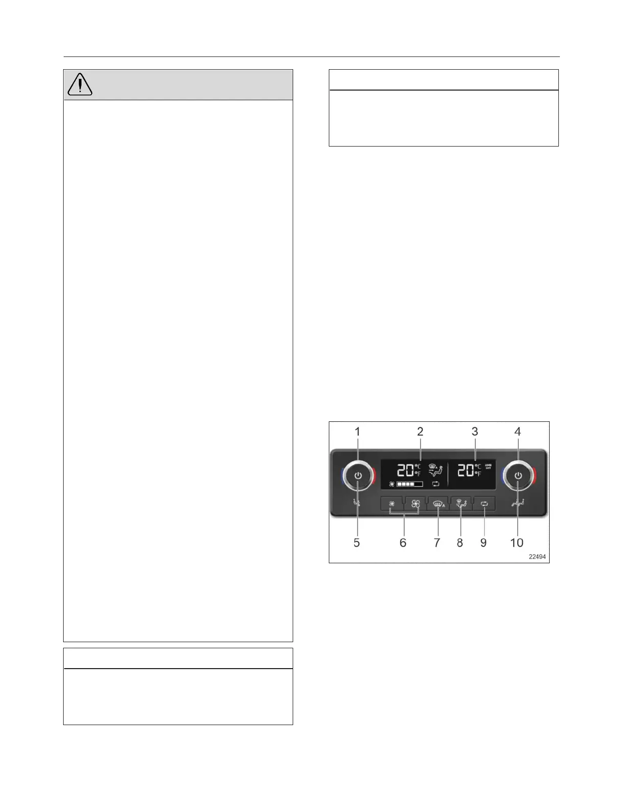 Loading...


