9-14 Technical Information
PA-1652 Operator's Manual H3-45 Coach
l Tag axle may be unloaded to provide better
traction in snow, mud and reduce the turning
radius and tire scrub at low cornering speed
SUSPENSION
Goodyear rolling lobe type air springs (bellows)
are used throughout.
I-BEAM AXLE FRONT SUSPENSION
2 Bellows;
2 Shock absorbers;
4 Radius rods;
1 Transverse radius rod;
1 Height control valve;
1 sway bar;
DRIVE AXLE
4 Bellows;
4 Shock absorbers;
3 Radius rods;
1 Panhard rod;
2 Height control valves;
1 Anti-roll bar;
TAG AXLE
2 Bellows;
2 Shock absorbers;
3 Radius rods;
1 Panhard rod;
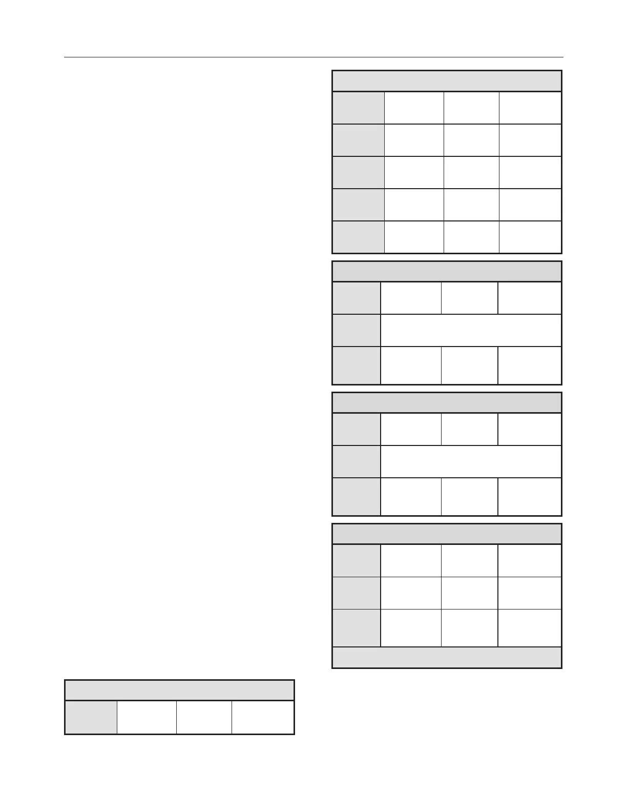
ALIGNMENT SPECIFICATIONS
Use static wheel alignment systems which work
with angle measurements only, such as Josam or
Hunter systems. Static alignment specifications
are listed in the following tables:
FRONT I-BEAM AXLE
Minimum
value
Nominal
value
Maximum
value
FRONT I-BEAM AXLE
Right
camber
-0.25° 0.125° 0.375°
Left
camber
-0.25° 0.125° 0.375°
Right
caster
2.0° 2.75° 3.5°
Left
caster
2.0° 2.75° 3.5°
Total
toe
0.04° 0.06° 0.08°
DRIVE AXLE - MERITOR
Minimum
value
Nominal
value
Maximum
value
Thrust
angle
±0.11°
Total
toe
0.18°
toe-in
0°
0.18°
toe-out
DRIVE AXLE - ZF A132
Minimum
value
Nominal
value
Maximum
value
Thrust
angle
±0.11°
Total
toe
0.15°
toe-in
0°
0.15°
toe-out
TAG AXLE
Minimum
value
Nominal
value
Maximum
value
Thrust
angle*
-0.02° 0 0.02°
Total
toe
0.12°
toe-in
0°
0.02°
toe-out
(*) Use the drive axle as reference

 Loading...


