18 © 2015 Proceq SA
5.3 Measure Cover Depth
Once the rebar grid has been located the cover can be measured.
NOTE! In all cases mentioned under 5.3.2 and 5.3.3 (especially when the measured cov-
er is close to a minimum required one), it is advisable to expose at least one first layer
rebar of each rebar arrangement to determine the real cover. The measured covers can
then be compared and if necessary corrected with the real cover.
5.3.1 Cover Measurement on areas with sufficient Spacing of the Rebars
A sufficient spacing is equal to or larger than the minimum spacing defined in 3.4.4.
Set the Rebar Diameter
An accurate knowledge of the rebar diameter will also give best cover depth results.
The default Reference Rebar Diameter set in the instrument is 16 mm or #5. This can be seen in the
status row at the top of the display screen.
If you already know the actual rebar
dia
meter, select the icon in the menu to set this as the reference.
NOTE! If you DO NOT know the rebar diameter, then proceed to 5.4. to measure the
diameter first. But this is only possible to a maximum cover of 60 mm to 65 mm / 2.5”
to 2.6”.
Now you can set the measured diameter.
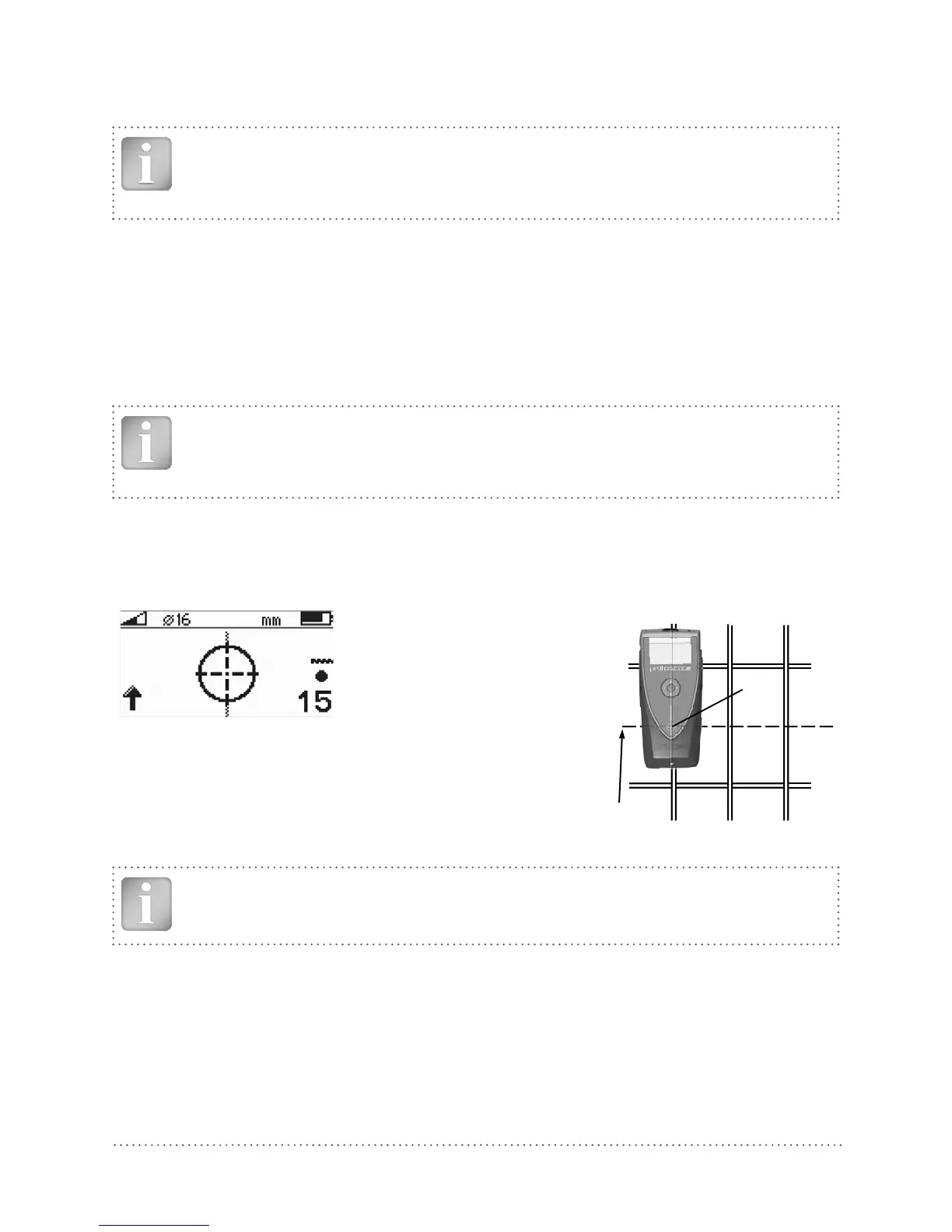
Read the Cover Depth
Place the centre line of the Profoscope directly over the rebar and read off the cover depth.
e. g.
Cover depth = 15 mm
Midpoint line
MC (4)
Fig 22: Display of cover depth Fig 23: Cover depth measurements
NOTE! Ensure that the Centre Line (9) is directly over and in line with the rebar and that
the MC (4) is ideally at the midpoint between two rebars of the second layer.