22 © 2015 Proceq SA
5.4 Measure Rebar Diameter
In case the real rebar diameter is not known, the Profoscope can accurately determine the diameter
of a rebar under certain conditions.
NOTE! The determination of the rebar diameter with Profoscope is limited to a maximum
cover of 64 mm / 2.5”.
The tutorial chapter on the pulse induction principle describes the limitations of the technology and
clearly outlines the conditions whereby accurate readings of rebar diameter CANNOT be made if
there is too much interference from neighboring rebars or other metallic objects within the sphere
of influence.
We present four working methods which are recommended to obtain the best results.
NOTE! In all cases mentioned under 5.4.2 and 5.4.3, it is advisable to expose at least one
first layer rebar of each rebar arrangement to measure the real diameter. The obtained
diameter values can then be compared and if necessary corrected with the measured
real diameter.
5.4.1 Diameter Measurement on Areas with sufficient Spacing of the Rebars
A sufficient spacing is equal or larger as the minimum spacing defined in 3.4.4.
Method 1
Map out a rebar grid on a test surface and then select one rebar from the grid that has sufficient
spacing from other rebars.
Step 1 Create a rebar grid as described in 5.2.4.
Step 2 Select one rebar that has the largest spacing from neighboring rebars.
Step 3 Use a ruler and confirm that the spacing is at least as indicated in 3.4.4. If not, redo
Steps 1 and 2 until a rebar is located with the required spacing to a neighboring rebar.
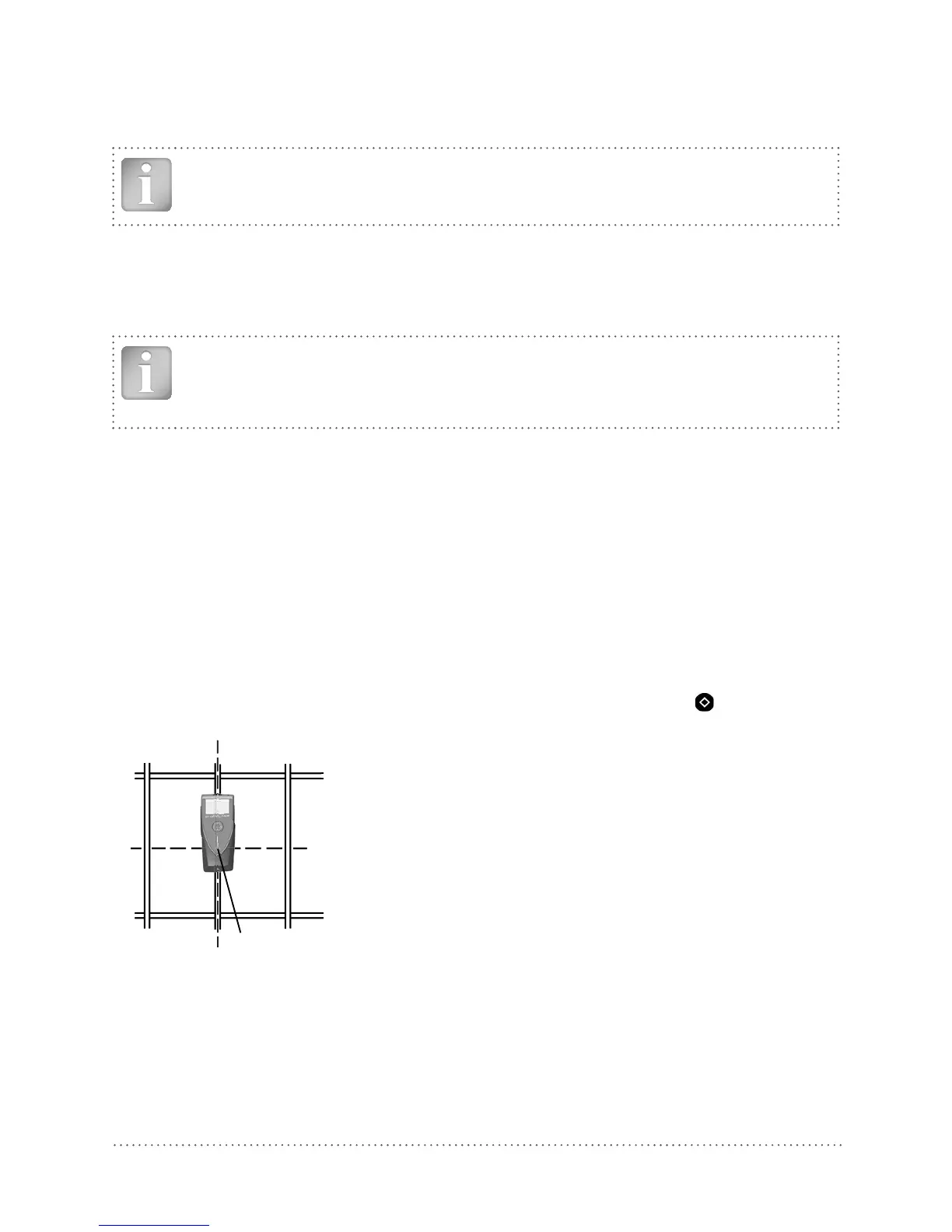
Step 4 Place the MC (4) of the Profoscope over the rebar at the midpoint line of the rebars run-
ning crosswise to the rebar under test and click the Function Key (6)
on the left side.
Midpoint line
CL (9)
MC (4)
Fig 27: Diameter measurement