© 2015 Proceq SA 23
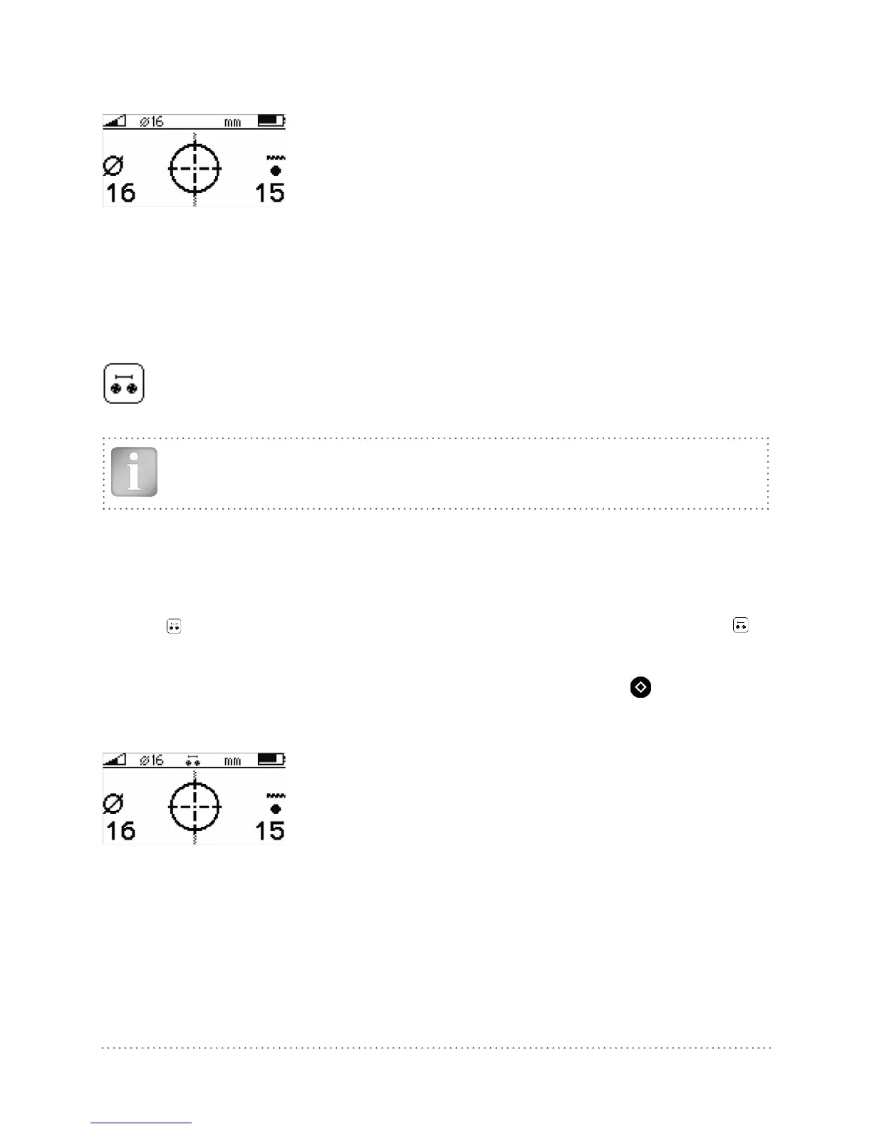
The measured rebar diameter appears for a few seconds instead of the signal strength arrow on the
bottom left corner of the display.
Fig 28: Display of measured diameter
Note down the rebar diameter. With the Profoscope+ you may also store the measured diameter
(see 6.8.1).
5.4.2 Diameter Measurement on Areas with insufficient Spacing of the Rebars
(Neighboring Rebar Correction)
Method 2
As described in the tutorial neighboring rebars that are within the sphere of influence will also
be detected by the Profoscope and will affect cover depth and diameter estimation results.
A insufficient spacing is smaller as the minimum spacing defined in 3.4.4.
The effects of neighboring rebars can be mitigated by keying-in a correction value.
NOTE! This works only for rebars of the same layer running in parallel to the rebar under
test.
Step 1 Create a rebar as described in 5.2.4.
Step 2 Select one rebar that has the largest spacing from neighboring rebars.
Step 3 Use a ruler to measure the spacing. In case the spacing from the rebar under test to a
neighboring rebar is equal or less than 130 mm / 5.2” go to the main menu, select the icon
and input the measured spacing. Verify that neighboring rebar correction symbol is
active in the status line at the top of the display.
Step 4 Place the MC (4) of the Profoscope over the rebar at the midpoint line of the rebars run-
ning crosswise to the rebar under test and click the Function Key (6)
on the left side.
The measured rebar diameter appears for a few seconds instead of the signal strength arrow on the
bottom left corner of the display.
Fig 29: Display of measured diameter with neighboring rebar correction set
Note down the rebar diameter. With the Profoscope+ you may also store the measured diameter
(see 6.8.1).
Try it out on the start-up test kit.