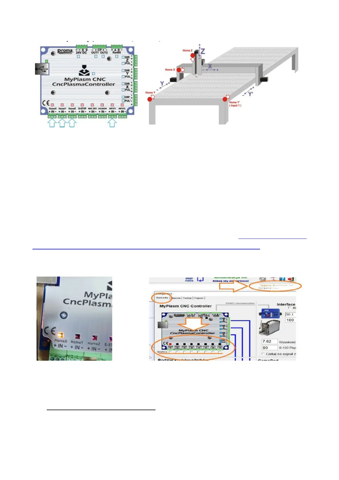
Example of basic sensor arrangement on a machine with a two-sided Y-
axis drive ( Y + Y' ).
Separate home switches for the Y + Y' drives allow auto squaring of
the gantry during reference travel. The homing switches need to have
adjustment to allow the squareness to be set.
The input lights on the motherboard indicate the 'physical' state of the
input, which should change depending on whether the sensor is active or
not.
In the case of NC sensors/contacts, it is possible to reverse the signal in the
"ELECTRONICS" tab in the software, where the correct operation of the
inputs can be checked. The input light in the program should light up (
RED ) when a sensor is activated. In the "rest" position when no sensor is
activated all the lights in the program should be inactive ( BLACK ).
The status of the controls is also displayed in the main programme window
which makes it much easier to locate any problems.
If the Home/Limit input is activated, operation is stopped in an
emergency and further operation is blocked. To ignore the input ( e.g.
to "downshift" from the sensor ), press the manual travel arrows with
the RIGHT MOUSE BUTTON.
19



 To Next Page