EasyManua.ls Logo

Protec OPTIMAX 2010 NDT - Page 45

Protec OPTIMAX 2010 NDT
58 pages
Print Icon
To Next Page IconTo Next Page
To Previous Page IconTo Previous Page
Loading...
OPTIMAX
2010 NDT
User Manual
516
0
-
0
-
PROTEC GmbH & Co. KG, In den Dorfwiesen 14, 71720 Oberstenfeld, Germany
45
von
58
Pos. Order No. Description
-
1163
-
0
-
0300
Roller rack, developer
NDT
-
1163
-
0
-
0400
Roller rack, fixer
NDT
-
1163
-
0
-
0600
Roller rack, dryer
NDT
100
0170
-
0
-
0301
Side plate developer with shafts
(
left
)
1170
-
0
-
0301
Side plate developer
(
right
)
0170
-
0
-
0401
Side plate fixer with shafts
(
left
)
1170
-
0
-
040
1
Side plate fixer
(
right
)
102
1140
-
0
-
3800
Guide bar straight, short
103
1140
-
0
-
4500
Guide bar with nose
104
1140
-
0
-
3700
Guide bar, curved
105
1170
-
0
-
0304
Flat spring 55
106
3079
-
8
-
5013
Screw
M4x10, A4
107
3009
-
3
-
4023
Hexagonal nut
M4, A4
108
1140
-
0
-
0301
PU
-
roller
35 g
round
109
1170
-
0
-
0310
Driver shaft
Rack
110
1101
-
0
-
0302
Chain gear t
= 16 D
-
hole
111
1101
-
0
-
0304
Chain gear t
= 32
round hole
112
1101
-
0
-
0303
Chain gear t
= 32 D
-
hole
113
1170
-
0
-
0302
Worm gear
114
1101
-
0
-
0305
Bushing without clearance
115
1101
-
0
-
0317
Bushing big, black
116
2014
-
0
-
0001
Circlip
117
0170
-
0
-
0601
Side plate dryer with shafts (left)
1170
-
0
-
0602
Side plate dryer (right)
119
1140
-
0
-
0302
Rubber roller
35
120
1140
-
0
-
0605
Air jet
(35)
121
1170
-
0
-
0604
Dryer plate, large
122
1170
-
0
-
0603
Dryer plate, small
123
1170
-
0
-
0303
Fl
a
t spring
35
124
1163
-
0
-
0307
Roller NDT
125
1161
-
0
-
3900
Guide bar 2,
curved
without nose,
without ribs
126
1161
-
0
-
4000
Guide bar 2, curved with nose, without ribs
127
1101
-
0
-
0317
Bearing bush, large , black
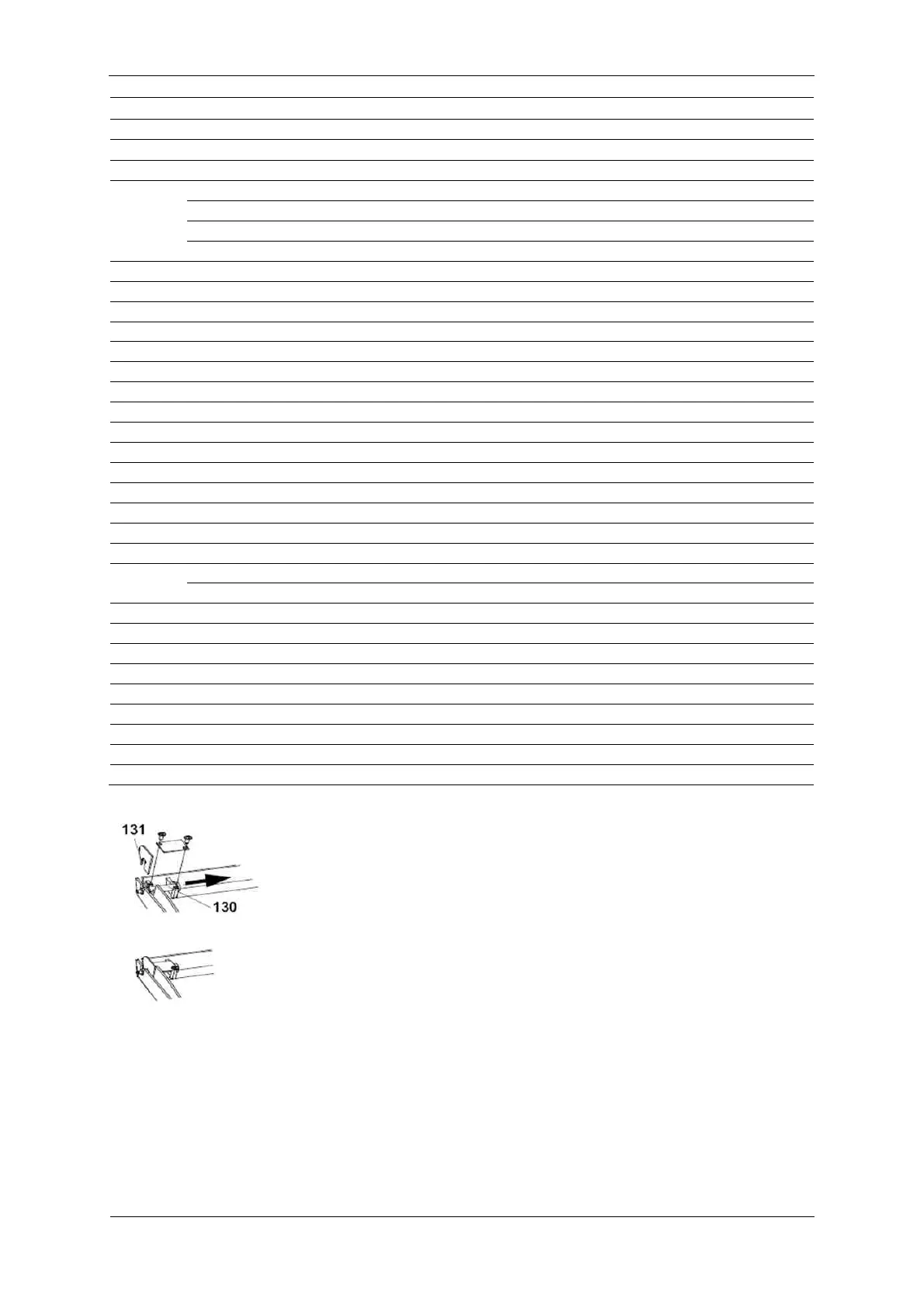
The light protection cover can be removed. This
is necessary to gain access
to the film detection switches and the developer level switch. To remove
it, pull off the blind (131) on the right side (!) of the cover and the pull the
indexing bolt (130) from the support toward the inside. The cover can now
be removed to the top. Remark: The left indexing bolt remains completely
installed.

Table of Contents

Related product manuals