User Manual
PROTEC GmbH & Co. KG, In den Dorfwiesen 14, 71720 Oberstenfeld, Germany
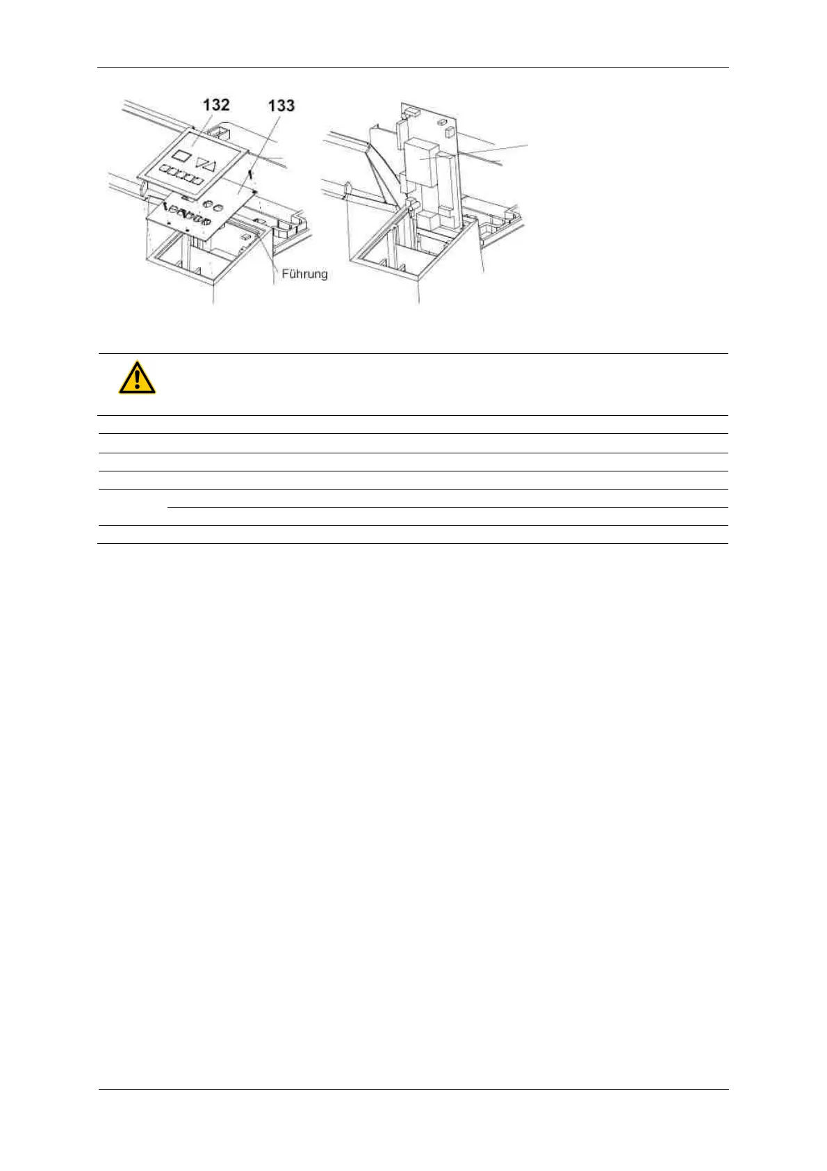
Once the operating panel
PCB has been removed, the
control unit can be removed.
Please do not lift the control
unit out further than shown
in the illustration. A guide on
the top edge allows to
position the control unit for
service purposes.
WARNING!
The heat sink is not earthed
Pos. Order No. Description
Blind for light protection cover
Control panel foil, 2 pump version
8.2 Tips and Tricks
8.2.1 Removal of control PCB
To reach the screws of the control PCB, remove the film covering the buttons by approx. 20 mm on the
top and bottom edges (lift it, see illustration top left).
8.2.2 Stop start-cycle
The start-cycle (after switching the machine on) can be manually interrupted. To stop start-cycle, press
both arrow-buttons (2+3) simultaneously. The start-cycle may only be interrupted for service purposes.
8.2.3 Display of machine information
When during the start-up cycle one of the arrow-buttons is pressed then various machine information
will be displayed.
8.2.3.1 Arrow button “Up”:
The software version is displayed as long as you press the button.
8.2.3.2 Arrow button “Down”:
The number of film cycles is displayed as long as you press the button. Not the decimal point. Since the
display has two digits only, the value needs to be converted:
XX : value x 10 = number of films
XX. : value x 100 = number of films
X.X : value x 1,000 = number of films
X.X. :value x 10,000= number of films
9.9. : more than 990,000 films