ABOUT THE SYSTEM LED DEFINITIONS
1-11
LED Definitions
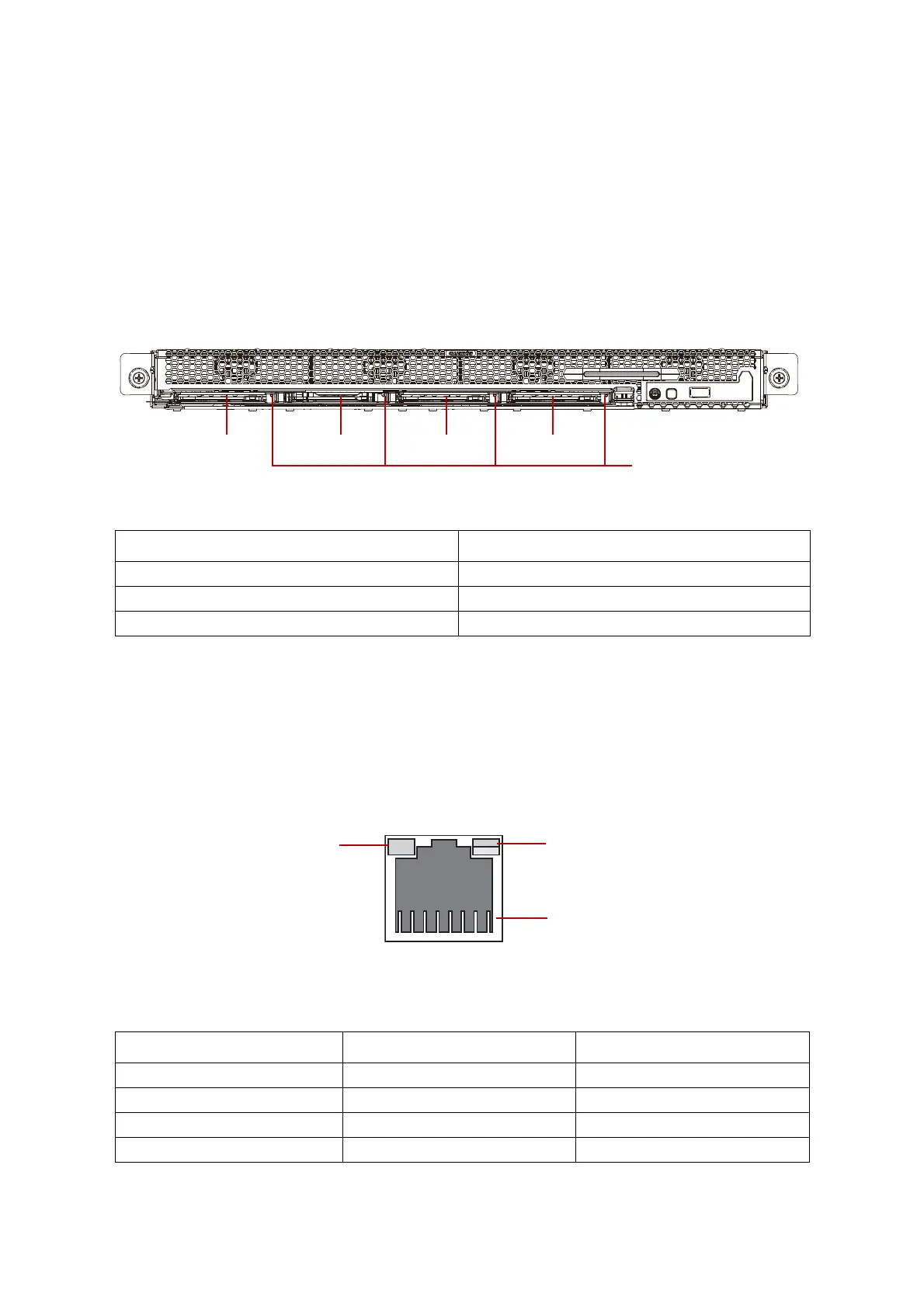
Front SAS/SATA HDD/SSD LED
The system features storage drive cage supporting up to 4x 2.5” SAS/SATA HDD/SSD
(7mm) on front bottom chassis.
Each carrier has one HDD/SSD Present / Fault LED. See the following illustration and table
for details.
Table 1.8: Front bottom 7mm 2.5” SAS/SATA HDD/SSD LED Description
LAN Port LED
The system mainboard has two i350 Ethernet controller.
Each RJ45 connector has two built-in LEDs. See the following illustration and table for
details.
Figure 1-7. RJ45 LAN Connector
COLOR STATUS
Blue On Continuously Drive Access / Drive present
Amber On HDD Failed / Drive present
Off Slot Empty
Table 1.9: RJ45 LED Description
STATUS LINK / ACTIVITY LED SPEED LED
Unplug Off Off
1G Link with Active Green blinking Amber On
100M Link with Active Green blinking Green On
10M Link with Active Green blinking Off
SSD0 SSD1 SSD2 SSD3
7.5mm HDD/SSD
Present / Fault
LED
Link/Activity
Speed
PIN 1
Location