• Step 2 - For the rst ight the calibration will capture additional data to ne
tuned the calibration
• an “!” will be displayed next to the home arrow indicating that it is in learning
mode
It is only necessary to do this once, but it may be necessary to recalibrate the compass
if you have moved a signicant distance away from where you performed the initial
calibration -Such as when traveling internationally.
RSSI
The QQ190™ has many different sources to read RSSI; Analog (voltage), Digital (PWM)
and Via BST.
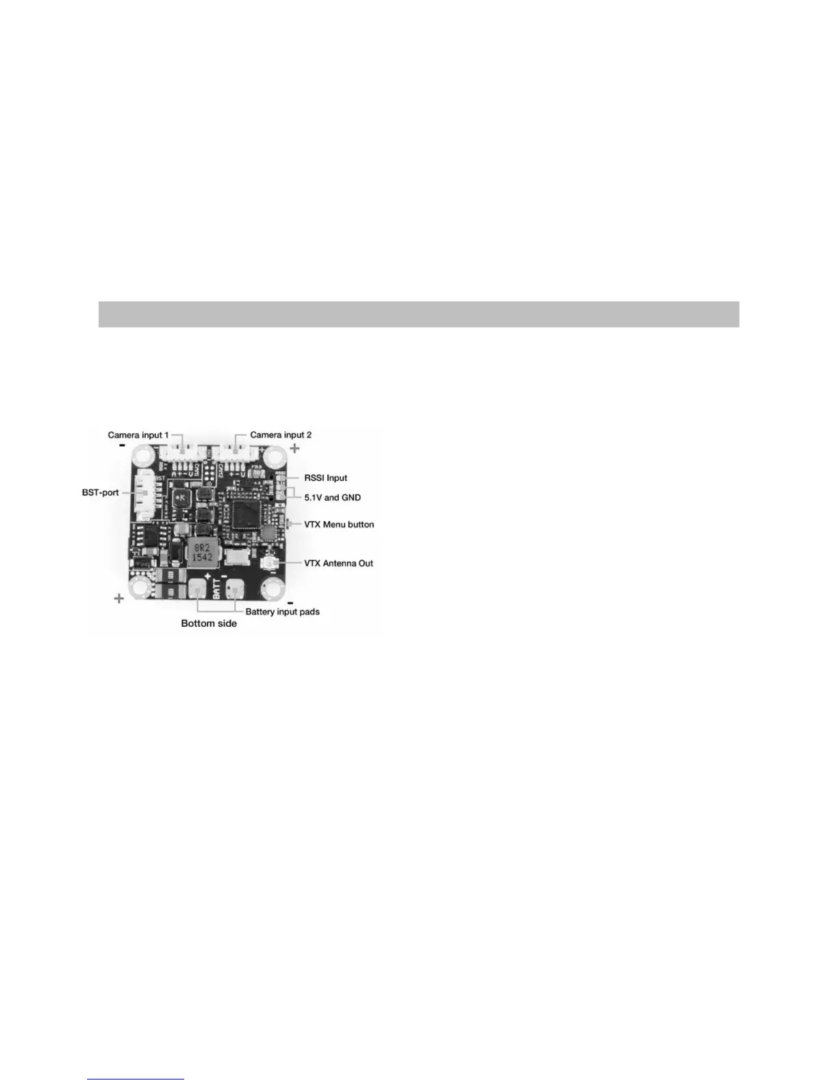
To connect an analog or digital RSSI signal from your receiver, solder your RSSI signal
wire to the pad on the bottom of the FPVision
layer of the electronics stack labeled “RSSI”.
If analog (voltage) or digital (PWM) is used,
the maximum and minimum signal strength
has to be recorded using the RSSI calibration
procedure.
•Source - Off/CrossFire/EzUHF OSD Link/
Digital
• (PWM)/Analog (voltage) - RSSI signal
source type
• POWERCUBE BST Bonus: It is also possible to use RSSI sent via a PPM channel
from the transmitter if connected via Blacksheep Telemetry (Crossre)
• Alarm - Enable/Disable - Display a textual warning and the RSSI read-out will
blink when the signal is critical
• Calibration - Used to set the max. (100%) and min. (0%) value for the signal
source.
 Loading...