Quantech
120
Form QTC3-NM1
Issue date: 12/19/2023
Section 6: Commissioning
fore placing the unit back in service, valves should be
opened and power must be switched ON (if power is
removed for more than 8 hours) for at least 8 hours (24
hours if ambient temperature is below 86°F [30°C])
before the unit is restarted.
Sporlan EEV interface board
Verify the jumper and dip switch settings, Figure 38 on
page 119, during a chiller start-up for QTC3 and QWC3
chillers with Sporlan Electronic Expansion Valves.
With the IB-G unpowered, select the input signal of 0
V to 10 V by installing the supplied jumper to number
1 of the 5 pin locations shown in the left hand side of
EEV board. Set numbers 1 to 3 of the DIP switches in
accordance with the unit models. Set numbers 4 to 8 in
accordance with the table shown in Figure 38 on page
119. For QTC3 chillers, DIP switch number 6 must be
set to ON for a quicker EEV response.
F/ protection
Verify all sources of electrical supply to the unit are
taken from a single point of isolation. Check that the
maximum recommended fuse sizes given in Section 5:
Technical data has not been exceeded.
Preparation, with power on
Perform the commissioning using the de-
tailed checks outlined. Refer to the Equip-
ment Pre-Startup And Startup Checklist
(Form 150.72-CL1) as the commissioning
procedure is carried out.
Apply power to the chiller. Turn on the option panel
circuit breaker if supplied.
The machine is now live!
Low switch
Verify a chilled water flow switch is correctly fitted in
the customer’s piping on the cooler outlet, and wired
into the control panel correctly using shielded cable.
There should be a straight run of at least 5 pipe diam-
eters on either side of the flow switch. The flow switch
should be connected to terminals 13 and 14 of XTBC1
on the panel.
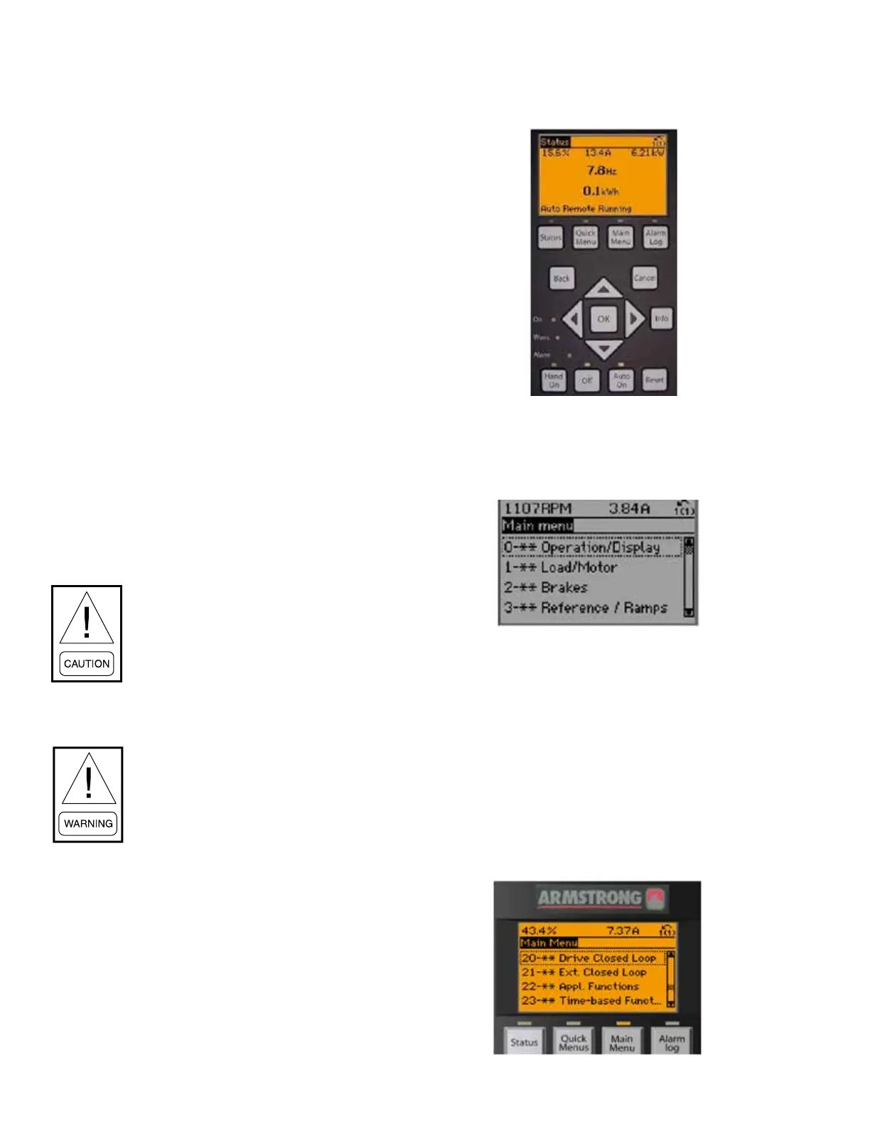
Commissioning the pump VFD
1. Put pump in HAND mode.
LD18418
2. Change parameter 0-20 (default value is option
1601 – “Reference [Unit]”) to option 1850 “Sen-
sorless Readout” to display Sensorless ow read-
out on top le corner of screen.
LD18419
3. Change parameter 0-22 (default value is option
1610 – “Power [kW]”) to option 1654 “Feedback
1 [unit]” to display Sensorless pressure readout on
top right corner of screen.
4. Check with customer regarding new actual ow
and head and verify what ow is required. Ramp
the pump up or down to achieve requested ow.
Record the VFD sensorless ow and pressure –
this will be your new setpoint.
5. Set parameter 20-21 to the Sensorless Pressure
readout taken in the previous step.
LD18420