Quantech
187
Section 9: Service and troubleshooting
Form QTC3-NM1
Issue date: 12/19/2023
9
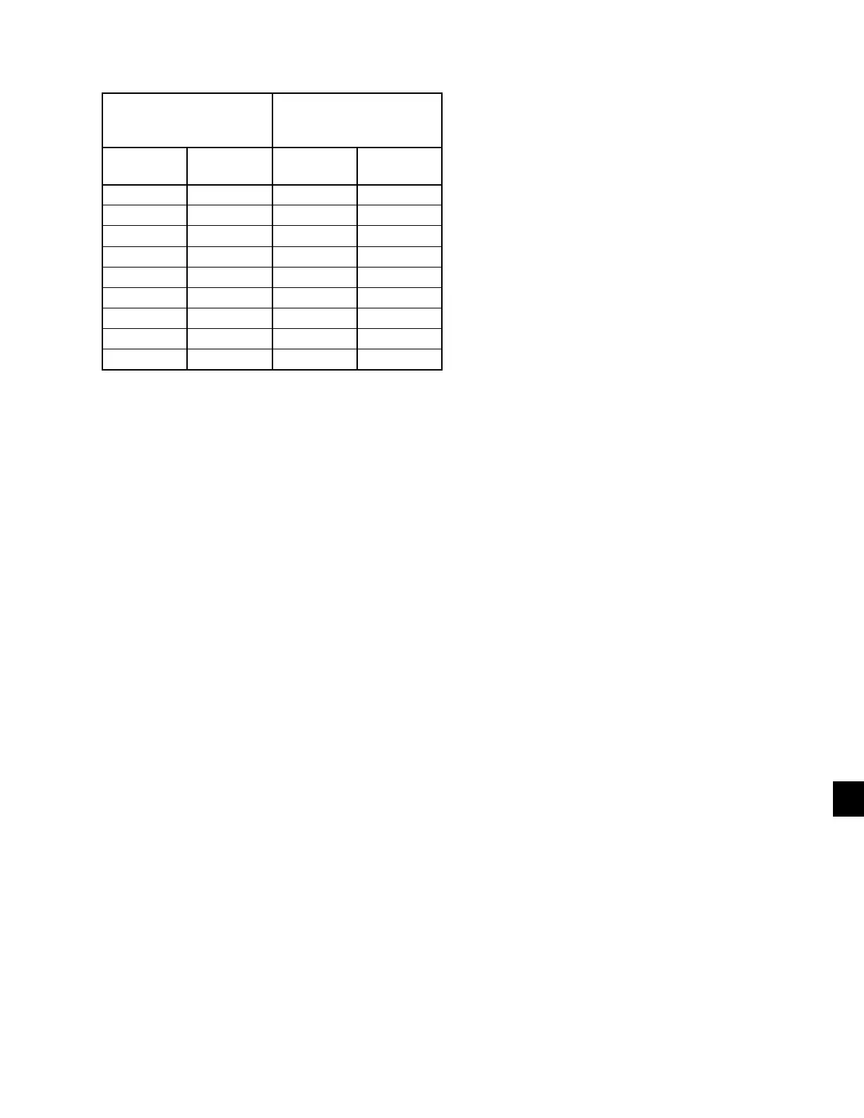
Table 33: Pressure Transducers
0-400 PSIG SUCTION
PRESSURE
TRANSDUCER
0-600 PSIG DISCHARGE
PRESSURE
TRANSDUCER
PRESSURE
PSIG
VOLTAGE
VDC
PRESSURE
PSIG
VOLTAGE
VDC
0 0.5 0 0.5
50 1.0 75 1.0
100 1.5 150 1.5
150 2.0 225 2.0
200 2.5 300 2.5
250 3.0 375 3.0
300 3.5 450 3.5
350 4.0 525 4.0
400 4.5 600 4.5
RED WIRE = 5V, BLACK WIRE = 0V, WHITE/GREEN WIRE = SIGNAL
TEST POINTS:
Suction Pressure:
System 1:
...............................................
Microboard J7-10 to J7-9
System 2:
...............................................
Microboard J9-10 to J9-9
Discharge Pressure:
System 1:
...............................................
Microboard J7-11 to J7-7
System 2:
...............................................
Microboard J9-11 to J9-7
V = (Pressure in psig x .01) + 0.5
or
V = (Pressure in barg x .145) + 0.5
where V = DC voltage output
Pressure = pressure sensed by transducer
The I/O board connections for the Discharge
Transducers are as follows.
System 1 discharge transducer
J7-6 = +5 VDC regulated supply to transducer.
J7-11 = VDC input signal to the microboard. See the
formula above for voltage readings that cor-
respond to specific discharge pressures.
J7-7 = +5 VDC return
J7-2 = drain (shield connection = 0VDC)
System 2 discharge transducer
J9-6 = +5 VDC regulated supply to transducer.
J9-11 = VDC input signal to the microboard. See the
formula above for voltage readings that correspond to
specific discharge pressures.
J9-7 = +5 VDC return
J9-2 = drain (shield connection = 0 VDC)
The suction transducers have a range from 0 to 400
psig (27.5 barg). The output will be linear from
0.5 VDC to 4.5 VDC over the 400 psig (27.5 barg)
range. Following is a formula that can be used to verify
the voltage output of the transducer. All voltage read-
ing are in reference to ground (unit case).
V = (Pressure in psig x 0.02) + 0.5
or
V = (Pressure in barg x 0.29) + 0.5
where V = DC voltage input to microprocessor
Pressure = pressure sensed by transducer
Following are the I/O board connections for the Suc-
tion Transducer.
System 1 suction transducer
J7-5 = +5 VDC regulated supply to transducer.
J7-10 = VDC input signal to the microboard. See the
formula above for voltage readings that cor-
respond to specific suction pressures.
J7-9 = +5 VDC return.
J7-1 = drain (shield connection = 0 VDC).
System 2 suction transducer
J9-5 = +5 VDC regulated supply to transducer.
J9-10 = VDC input signal to the microboard. See the
formula above for voltage readings that
correspond to specific suction pressures.
J7-9 = +5 VDC return.
J7-11 = drain (shield connection = 0VDC).
Digital outputs
See the unit wiring diagram and Figure 52 on page
188. The digital outputs are located on TB7, TB8, and
TB9 and TB-10 of the microboard. All outputs are 120
VAC with the exception of TB8-6 to TB8-7 which are
the contacts that can be used for a remote evaporator
pump start signal. The voltage applied to either of these
terminals would be determined by field wiring.