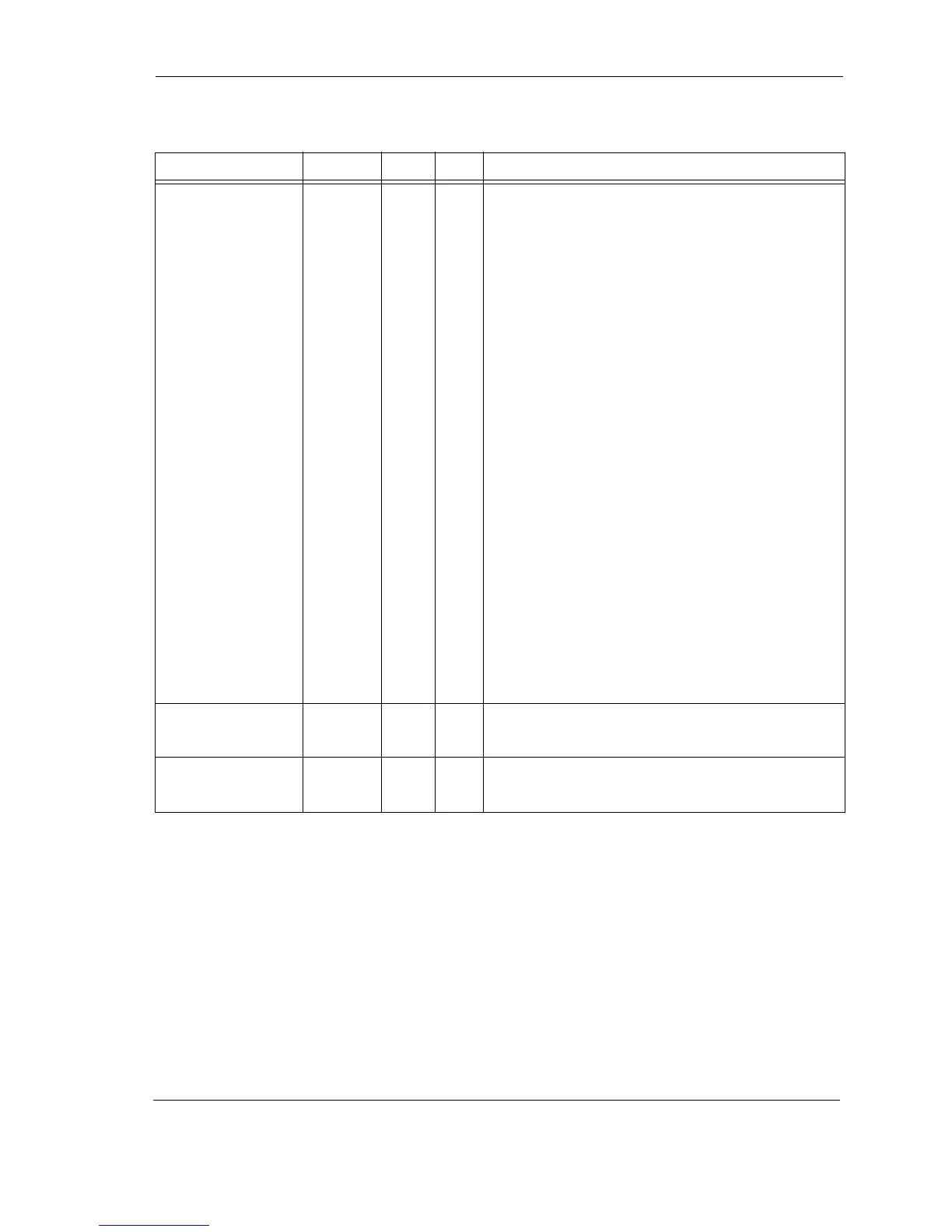
ATA Bus Interface and ATA Commands
Quantum Fireball Plus AS 10.2/20.5/30.0/40.0/60.0 GB AT 6-5
Passed Diagnostics PDIAG– I/O 34 Drive 0 (Master) monitors this Drive 1 (Slave) open-
collector output signal, which indicates the result
of a diagnostics command or reset. The drive has a
10K pull-up resistor on this signal.
Following the receipt of a power-on reset,
software reset, or RESET– drive 1 negates PDIAG–
within 1 ms. PDIAG– indicates to drive 0 that drive
1 is busy (BSY=1). Then, drive 1 asserts PDIAG–
within 30 seconds, indicating that drive 1 is no
longer busy (BSY=0) and can provide status
information. Following the assertion of PDIAG–,
drive 1 is unable to accept commands until drive 1
is ready (DRDY=1)—that is, until the reset
procedure for drive 1 is complete.
Following the receipt of a valid EXECUTE DRIVE
DIAGNOSTIC command, drive 1 negates PDIAG–
within 1 ms, indicating to drive 0 that it is busy
and has not yet passed its internal diagnostics. If
drive 1 is present, drive 0 waits for drive 1 to assert
PDIAG– for up to 5 seconds after the receipt of a
valid EXECUTE DRIVE DIAGNOSTIC command.
Since PDIAG– indicates that drive 1 has passed its
internal diagnostics and is ready to provide status,
drive 1 clears BSY prior to asserting PDIAG–.
If drive 1 fails to respond during reset
initialization, drive 0 reports its own status after
completing its internal diagnostics. Drive 0 is
unable to accept commands until drive 0 is ready
(DRDY=1)—that is, until the reset procedure for
drive 0 is complete.
Chip Select 0 CS1FX– IN 37 Chip-select signal decoded from the host address
bus. Used to select the host-accessible Command
Block Registers.
Chip Select 1 CS3FX– IN 38 Chip select signal decoded from the host address
bus. Used to select the host-accessible Control
Block Registers.
Table 6-1
Table 6-1 Table 6-1
Table 6-1
Drive Connector Pin Assignments (J1, Section C) (Continued)
SIGNAL
SIGNALSIGNAL
SIGNAL NAME
NAMENAME
NAME DIR
DIRDIR
DIR PIN
PINPIN
PIN DESCRIPTION
DESCRIPTIONDESCRIPTION
DESCRIPTION