ATA Bus Interface and ATA Commands
6-6 Quantum Fireball Plus AS 10.2/20.5/30.0/40.0/60.0 GB AT
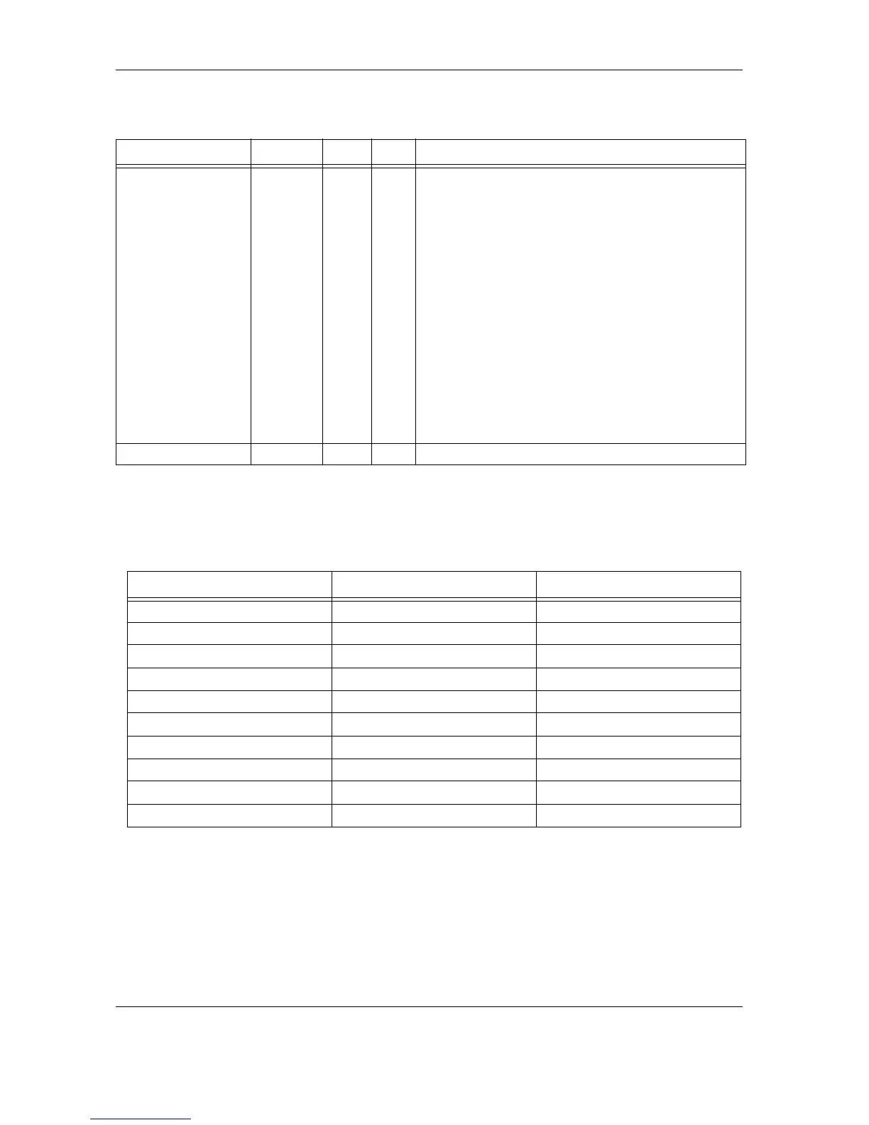
Series termination resistors are required at both the host and the device for
operation in any of the Ultra ATA/100 modes. Table 6-2 describes recommended
values for series termination at the host and the device.
Table 6-2
Table 6-2 Table 6-2
Table 6-2
Series Termination for Ultra ATA/100
Note:
Note:Note:
Note: Only those signals requiring termination are listed in this table.
If a signal is not listed, series termination is not required for
operation in an Ultra ATA/100 mode.
Drive Active/Slave
Present
DASP– I/O 39 A time-multiplexed signal that indicates either
drive activity or that drive 1 is present. During
power-on initialization, DASP– is asserted by drive
1 within 400 ms to indicate that drive 1 is present.
If drive 1 is not present, drive 0 asserts DASP– after
450 ms to light the drive-activity LED.
An open-collector output signal, DASP– is
deasserted following the receipt of a valid
command by drive 1 or after the drive is ready,
whichever occurs first. Once DASP– is deasserted,
either hard drive can assert DASP– to light the
drive-activity LED. Each drive has a 10K pull-up
resistor on this signal.
If an external drive-activity LED is used to monitor
this signal, an external resistor must be connected
in series between the signal and a +5 volt supply
in order to limit the current to 24 mA maximum.
Ground Ground — 40 Ground between the host system and the drive.
SIGNAL
SIGNALSIGNAL
SIGNAL HOST TERMINATION
HOST TERMINATIONHOST TERMINATION
HOST TERMINATION DEVICE TERMINATION
DEVICE TERMINATIONDEVICE TERMINATION
DEVICE TERMINATION
–/HDMARDY–/HSTROBE 33 W 82 W
DIOW–/STOP 33 W 82 W
CS0–, CS1– 33 W 82 W
DA0, DA1, DA2 33 W 82 W
DMACK– 33 W 82 W
DD 15 through DD0 33 W 22 W
DMARQ 82 W 22 W
INTRQ 82 W 22 W
IORDY/DDMARDY–/DSTROBE 82 W 22 W
DIOR 43 W
Table 6-1
Table 6-1 Table 6-1
Table 6-1
Drive Connector Pin Assignments (J1, Section C) (Continued)
SIGNAL
SIGNALSIGNAL
SIGNAL NAME
NAMENAME
NAME DIR
DIRDIR
DIR PIN
PINPIN
PIN DESCRIPTION
DESCRIPTIONDESCRIPTION
DESCRIPTION