© 2021 Radiodetection Ltd 20
If Isolation Joints are not used the PCM signal will be
present in both directions from the connection point.
Single rectifier providing impressed CP current to multiple
pipelines.
As above, disconnect pipeline and anode cables from the
rectifier.
Try to identify individual pipeline cables if they can be
separated at the rectifier, so that each pipeline can be
surveyed individually. This allows the maximum range to
be surveyed.
Connect the white PCM transmitter lead to one of the
pipeline cables, and the green connection lead to the
anode cable. Use the PCMx locator to help identify the
cables to the individual pipelines.
If the PCM transmitter signal is applied to more than one
pipeline at a time, the signal will be divided between
them, so the maximum range will be reduced.
Note: The pipe section which needs the most cathodic
protection current will also have the most PCMx
current, so using the PCMx Locator to measure the
current on all the pipe sections fed from the
rectifier will indicate the section with the worst CP
faults. This is a quick and easy guide to coating
quality.
5.2 When a rectifier is not
available
Test Points
At some points of the test, there are Isolation joints with
cables to the surface.
Connect the PCM transmitter across the isolation joint.
Connect the white cable to the side of the pipeline that
you want to survey, and then the green cable to the other
side for the ground connection.
Fig. 5.3: PCM connection using test point
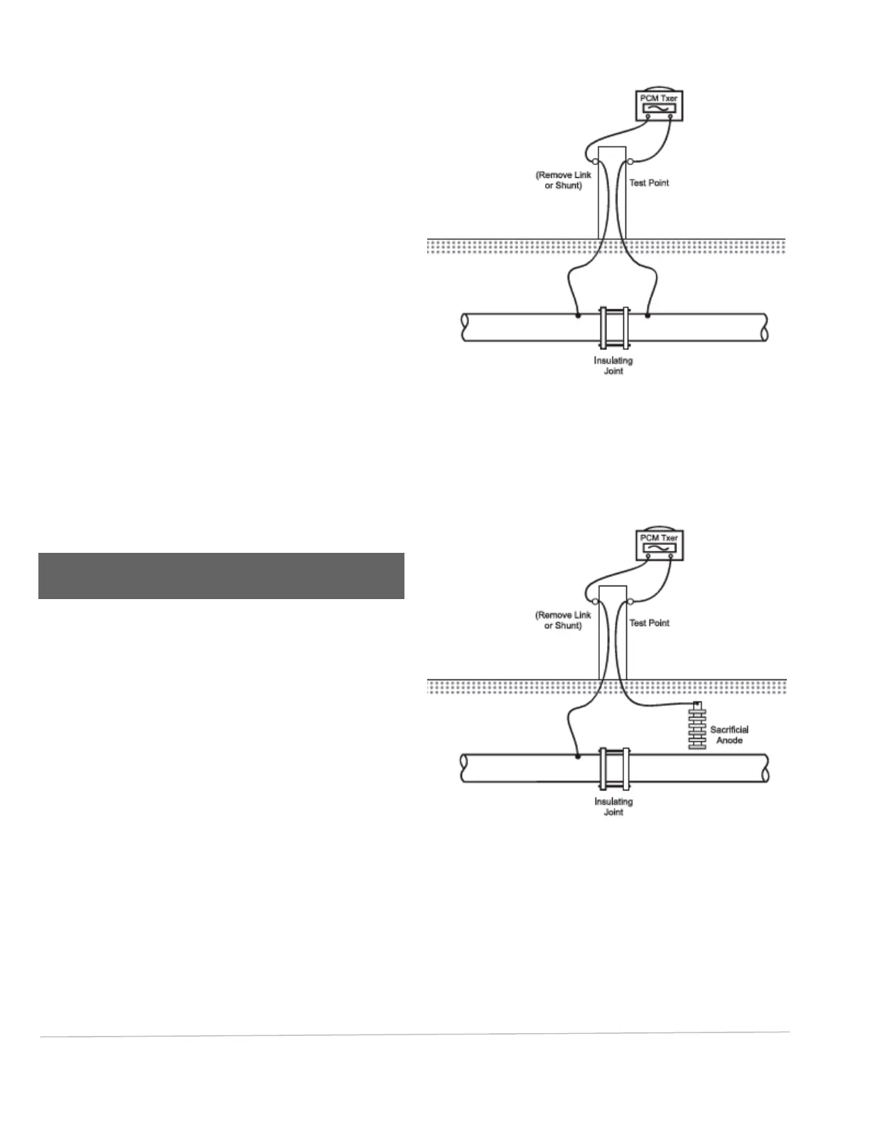
Sacrificial Anodes
You can use sacrificial anodes as a grounding point for
the PCM transmitter. This type of connection can be use
when there are no isolation joints. See Fig 5.4
Fig. 5.4: PCM connection using sacrificial anode for
grounding
Note: Some sacrificial anodes are connected directly to
the pipeline and not linked to test points. These
can be easily located as they cause large PCM
current loss.
Disconnect the link wire from pipeline to sacrificial anode
in the test point.